Improved illumination light control method

A light control and improved technology, applied in the direction of light guide, optics, optical components, etc., can solve the problem of high cost of light control program and space design, and achieve the effect of solving the problem of high cost and space design

Inactive Publication Date: 2015-11-18
CHENGDU QIULEI TECH
View PDF3 Cites 0 Cited by
  • Summary
  • Abstract
  • Description
  • Claims
  • Application Information

AI Technical Summary

Problems solved by technology

[0005] Compared with the prior art, the improved illumination light control method can well solve the problems of high cost and space design of the existing light control program

Method used


Image

  • Improved illumination light control method

Examples


Embodiment Construction

[0008] In order to make the purpose, technical solution and advantages of the present application clearer, the present application will be further described in detail below in conjunction with the accompanying drawings and specific embodiments.

[0009] In the following description, references to "one embodiment," "an embodiment," "an example," "example," etc. indicate that such described embodiment or example may include a particular feature, structure, characteristic, property, element, or limitations, but not every embodiment or example necessarily includes the specific feature, structure, characteristic, property, element or limitation. Additionally, repeated use of the phrase "according to one embodiment of the present application" does not necessarily refer to the same embodiment, although it may.

[0010] For simplicity, some technical features known to those skilled in the art are omitted from the following description.

[0011] According to an embodiment of the prese...


PUM


Abstract

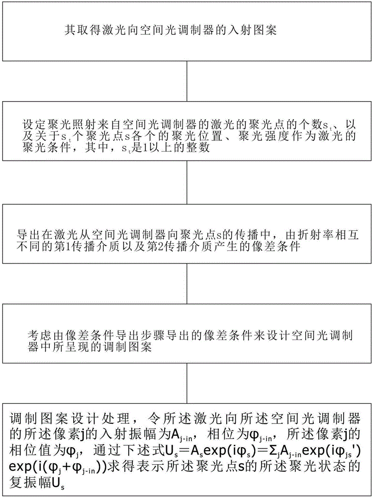
Provided in the invention is an improved illumination light control method. The method comprises: an irradiation condition obtaining step; to be specific, obtaining and using an incident pattern of laser to a spatial light modulator, a first refractive index n1 of a first propagation medium on a propagation path of the laser from the spatial light modulator to a focus point, and a second refractive index n2, different from the first refractive index, of a second propagation medium closer to the focus point side than the first propagation medium as laser irradiation conditions; and a light condensation condition setting steps; to be specific, setting the number st of condensation points for condensed irradiation on the laser from the spatial light modulator as well as respective condensation positions and condensation strength of the st condensation points as the condensation conditions of the laser. The st is an integer larger than 1.

Description

technical field [0001] In particular, the present invention relates to an improved illumination light control method. Background technique [0002] In recent years, research on optical integrated circuits, such as waveguides, optical splitters, and directional couplers, etc., has been fabricated three-dimensionally inside glass. As one of the methods of manufacturing such an optical integrated circuit, there is a method using a femtosecond laser. In this method, for example, by inducing impact at the converging point of the femtosecond laser light by two-photon absorption or the like, it is possible to locally change the refractive index of the glass. In addition, such focused irradiation of laser light on an irradiation object is widely used in various laser processing devices or laser microscopes for observing the scattering and reflection of laser light in addition to the production of optical integrated circuits. When a single laser beam emitted from a laser light sour...

Claims


Application Information

Patent Timeline
IPC IPC(8): G02B27/00G02B6/122
CPCG02B27/0012G02B6/122
Inventor 黄雷
Owner CHENGDU QIULEI TECH
Why Eureka
Try Eureka