Electric main shaft system modeling method taking features of combination portions into consideration

A system modeling and combination technology, applied in the general control system, control/regulation system, electrical program control, etc.

Active Publication Date: 2015-11-18
BEIJING UNIV OF TECH
View PDF12 Cites 11 Cited by
  • Summary
  • Abstract
  • Description
  • Claims
  • Application Information

AI Technical Summary

Problems solved by technology

In the usual electric spindle design analysis, the influence of joints is often ignored, or only a part of the joints is modeled and analyzed, but there is no complete theoretical modeling method that considers all joints

Method used


Image

  • Electric main shaft system modeling method taking features of combination portions into consideration
  • Electric main shaft system modeling method taking features of combination portions into consideration
  • Electric main shaft system modeling method taking features of combination portions into consideration

Examples


Embodiment Construction

[0017] The present invention implements a motorized spindle system modeling method considering the characteristics of joints. The implementation of the present invention will be described in detail below in conjunction with the accompanying drawings.

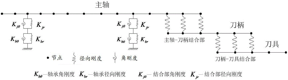
[0018] figure 1 It is a schematic diagram of the finite element model of the electric spindle system. As shown in the figure, the main shaft-tool holder-tool shaft segment is modeled by Timoshenko beam elements for finite element modeling. The stiffness of the spindle-bearing joint and the stiffness of the bearing are in a series relationship, and the support stiffness can be calculated according to the series formula. The main shaft-knife handle-tool joint is simplified as a distributed spring, and the spring interval is consistent with the length of the shaft segment unit. Step (1), identify the stiffness of the joint of the motorized spindle system

[0019] 1.1 Frequency response function method

[0020] The frequency res...


PUM


Abstract

The invention discloses an electric main shaft system modeling method taking features of combination portions into consideration. According to the method, first of all, based on a frequency response function method, the rigidity of the combination portion of an electric main shaft system is identified by use of a hammering experiment, then a finite element model of a main shaft-handle-cutter system is established through the mode of adding and deleting a transition unit at the tail end of a main shaft and a handle, and finally, bearing rigidity, and a rigidity matrix of a main shaft-bearing combination portion and a rigidity matrix of a main shaft-handle-cutter combination portion which are obtained through identification are added to the rigidity matrix of the electric main shaft system so that a complete electric main shaft system kinetic equation is obtained. According to the invention, the rigidity of the combination portions are identified by use of an experiment method, and a theoretical model of the electric main shaft system is established with the influences of the combination portions are taken into consideration, so that the influence rules of the rotating speed, the bearing rigidity, the rigidity of each combination portion and the like for the dynamic features of the electric main shaft system can be simultaneously analyzed. The method can provide guidance for design and application of an electric main shaft and also provides a theoretical basis for prediction of the cutting stability of the electric main shaft system.

Description

technical field [0001] The invention belongs to the field of dynamic analysis of the electric spindle system, and relates to a modeling method of the electric spindle system considering the characteristics of the joint. - A complete finite element dynamic model of the electric spindle system has been established for the tool joint. Background technique [0002] Motorized Spindle (MotorizedSpindle) is one of the key components of CNC machine tools. Its characteristic is that the machine tool spindle and the spindle motor are combined into one, the machine tool spindle is directly driven by the built-in motor, and the main transmission chain of the machine tool is shortened to zero, thus realizing the zero transmission of the machine tool. The electric spindle is usually supported by angular contact ball bearings, and the front end is connected with the tool holder and the tool through a tapered hole. Generally speaking, the electric spindle system includes four parts: spind...

Claims


Application Information

Patent Timeline
Patent Type & Authority Applications(China)
IPC IPC(8): G05B19/18
CPCG05B19/18G05B2219/32339
Inventor 赵永胜方翠王传国蔡力钢刘志峰
Owner BEIJING UNIV OF TECH
Why Eureka
Try Eureka