Leaky cable wrapping forming method

A technology of leaky cables and forming methods, applied in the direction of marking conductors/cables, manufacturing cables/conductors, insulating conductors/cables, etc., to achieve the effects of avoiding cross-folding, simple structure, and improving the pass rate

Active Publication Date: 2015-11-18
中山市博宇电线有限公司
View PDF6 Cites 5 Cited by
  • Summary
  • Abstract
  • Description
  • Claims
  • Application Information

AI Technical Summary

Problems solved by technology

The longitudinal wrapping platform is the reference working platform, and its surface is flat. The first longitudinal wrapping die, the second longitudinal wrapping die, the longitudinal wrapping cone, the lapping die, and the first sizing die are successively installed on the longitudinal wrapping platform. , and the second sizing die, the first longitudinal wrapping die and the second longitudinal wrapping die cooperate to form an inner streamlined mold cavity, a mandrel is fixed in the die cavity, and the mandrel is fixed on the longitudinal On the wrapping platform, the gap space between the mandrel and the mold cavity is used as the movement forming space of the copper strip. After the copper strip passes through the mold cavity, the copper strip and the cable core enter the longitudinal wrap forming conical cylinder at the same time, and then pass through the overlapping die, After the first sizing die and the second sizing die come out, the copper tape is wrapped longitudinally on the cable core to form the outer conductor of the leaky cable, and then squeezed on the sheath synchronously to form a leaky cable. Compared with the current process die, the present invention The leaky cable after processing, because the copper strip will not swing left and right during the forming process, completely solves the problems of copper strip slot deformation, copper strip breakage and position change, which improves product quality and achieves higher uniformity sex

Method used


Image

  • Leaky cable wrapping forming method
  • Leaky cable wrapping forming method
  • Leaky cable wrapping forming method

Examples


Embodiment

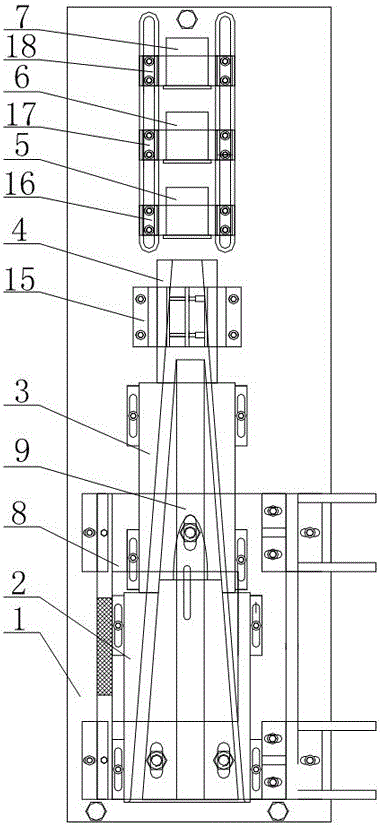
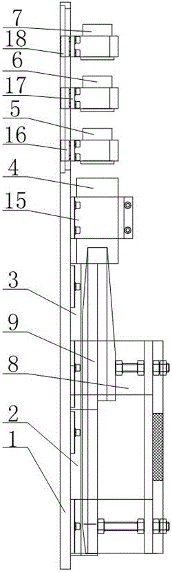
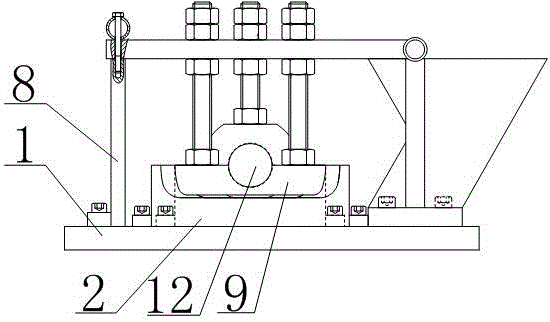
[0025] Such as Figures 1 to 6 As shown, a wrapping molding method for leaky cables of the present invention includes a longitudinal wrapping platform 1, on which a coaxial first longitudinal wrapping mold 2 and a second longitudinal wrapping mold 3 are sequentially installed, the first longitudinal wrapping mold 3 The mold cavity of the longitudinal wrapping mold and the second longitudinal wrapping mold 3 is connected into a streamlined mold cavity as a whole, and a mandrel support 8 is fixedly installed on the longitudinal wrapping platform 1, and the mandrel support 8 is positioned on the streamlined mold cavity. Directly above the cavity, a mandrel 9 is installed on the mandrel bracket 8. The mandrel 9 cooperates with the mold cavity to form a molding channel for the copper strip. The mandrel 9 is formed by connecting a conical plate 10 and a conical body 11. The conical body 11 A through hole 12 is provided on the axis of the conical plate 10 to form an inner layer feedi...


PUM


Abstract

The invention discloses a leaky cable wrapping forming method which comprises a longitudinal wrapping platform. The longitudinal wrapping platform is sequentially and coaxially equipped with a first longitudinal wrapping forming die, a second longitudinal wrapping forming die, a longitudinal wrapping forming conical barrel, a lapping die, a first sizing die and a second sizing die. Die cavities of the first longitudinal wrapping forming die and the second longitudinal wrapping forming die are connected into a whole streamline die cavity. The longitudinal wrapping platform is equipped with a core shaft support; the core shaft support is equipped with a core shaft; the core shaft is arranged in the whole streamline die cavity; and the core shaft cooperates with the first longitudinal wrapping forming die and the second longitudinal wrapping forming die to form a longitudinal wrapping type cavity. The method solves the problems of deformation of slots in a copper strip, tensile failure and position change of the copper strip since the copper strip does not swing left and right in the forming process, so that the quality of the product is improved, and higher uniformity is realized; and since the existence of a tongue coating, the two side edges of the copper strip are allowed to be always in the same position, the case of cross folding is prevented, and the qualified rate of the product is improved.

Description

technical field [0001] The invention relates to a mold for the communication cable manufacturing industry, in particular to a wrapping molding method for leaky cables. Background technique [0002] Leaky cable is the abbreviation of leaky coaxial cable (Leaky Coaxial Cable), which consists of four parts: inner conductor, insulating medium, outer conductor with periodic slots and sheath. During the transmission of the radio frequency signal inside the leaky cable, a part of the radio frequency signal is coupled to the external space through the outer conductor hole; the radio frequency signal in the outer space can also be coupled to the inside of the cable through the outer conductor hole. Therefore, the leaky cable has the dual functions of a radio frequency signal transmission line and a transceiver antenna. It is generally used in specific spaces where communication antennas are difficult to function, especially in specific spaces where separate antennas in mobile commun...

Claims


Application Information

Patent Timeline
Patent Type & Authority Applications(China)
IPC IPC(8): H01B13/34H01B13/26
CPCH01B13/00H01B13/10H01B13/22H01B13/24H01B13/26H01B13/2613H01B13/34
Inventor 吴光武
Owner 中山市博宇电线有限公司
Why Eureka
Try Eureka