Integrated connector end structure and preparing method thereof

A connector, integrated technology, applied in the direction of connection, connecting device parts, contact parts, etc., can solve the problems of high processing loss cost, easy product breakage, large material consumption, etc., to save material cost and improve production. Efficiency, the effect of small production consumables

Active Publication Date: 2015-11-18
FREEWON CHINA CO LTD
View PDF5 Cites 5 Cited by
  • Summary
  • Abstract
  • Description
  • Claims
  • Application Information

AI Technical Summary

Problems solved by technology

This kind of preparation method has the following disadvantages: 1. The traditional processing method is due to the forging and extrusion process of some materials, so that the fault 3 connected with the forged 1 and the unforged 2 is very prone to fracture and fall off, and subsequent sandblasting and extrusion cannot be carried out. Continuous electroplating and other product surface treatment processes cannot achieve reliable mass production defects; 2. The traditional processing method can only process some materials through forging and extrusion processes, and the thickness of the unforged part is thicker than 1.0mm. To achieve disc-shaped packaging, only one by one can be used for packaging, and continuous operation cannot be realized in mass production, and subsequent surface treatment processes such as sandblasting and electroplating can only be carried out one by one; 3. The copper material used is large. Part of the forging and extrusion process makes the thickness of the raw material more than 1.0mm, and the material consumption is large
Therefore, the traditional processing technology has defects such as easy breakage of the product, inability to achieve disc-shaped packaging, inability to perform continuous operations, and high processing loss costs.

Method used


Image

  • Integrated connector end structure and preparing method thereof
  • Integrated connector end structure and preparing method thereof
  • Integrated connector end structure and preparing method thereof

Examples


Embodiment 1

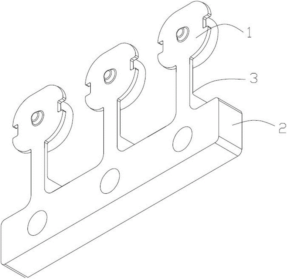
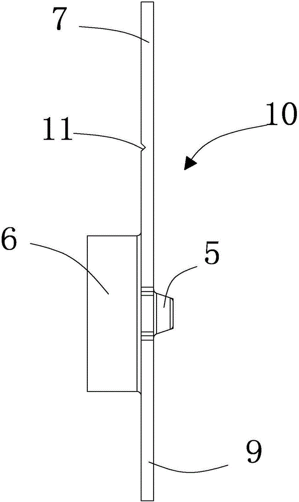
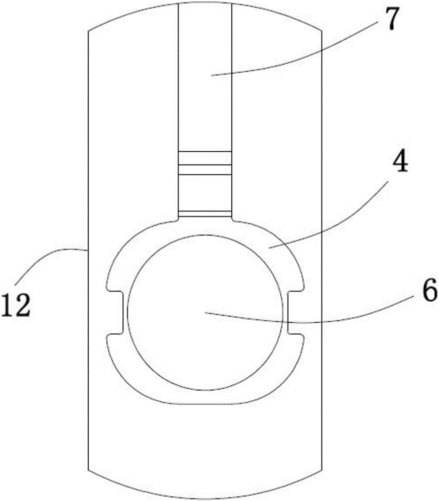
[0033] refer to Figure 2 to Figure 5 As shown, a one-piece connector head structure includes several head parts 4, and a first convex part 5 and a second convex part 6 are respectively arranged on both sides of the head part, and the head part, the first convex part and the second convex part The two convex parts are integrally formed, and the end part is connected with the strip part 8 through the connecting arm 7. The thickness of the end part, the thickness of the connecting arm and the thickness of the strip part are all the same.

[0034] Wherein, the thickness of the strip portion is 0.14-0.16mm, and the materials of the end portion, the first convex portion, the second convex portion, the connecting arm and the strip portion are all copper.

[0035] A number of positioning holes are evenly arranged on the surface of the material belt, which is convenient for the equipment to be accurately positioned during subsequent processing.

[0036] A method for preparing the one...

Embodiment 2

[0045] The difference between the second embodiment and the first embodiment is that the connection method in the step 3 is riveting, and the connecting arm is riveted together with the strip part during riveting, such as Image 6 shown. The method of riveting has the advantages of fast speed and reduced manufacturing cost, and the connection by welding is abandoned, thereby reducing the difficulty of the process.

[0046] The present invention is prepared by turning and stamping as a whole, has high equipment maturity, low manufacturing cost, and is suitable for mass production.


PUM


Abstract

The invention discloses an integrated connector end structure. The integrated connector end structure comprises a plurality of end parts. A first projection part and a second projection part are respectively arranged at two sides of each end part. The end parts, the first projection parts and the second projection parts are prepared in an integrated manner. The end parts are connected with a material belt part through connecting arms. The end parts, the connecting arms and the material belt part are identical in thickness. The preparing method comprises the following steps of: 1) lathing end part stocks; 2) punching the material belt part, 3) carrying out an integral connection process; and 4) carrying out a punching molding process. The integrated connector end structure is simple in structure, convenient to prepare and liable to crack, disk-shaped packaging is realized, and the production cost is low.

Description

technical field [0001] The invention relates to the field of connection ends, in particular to an integrated connector end structure and a preparation method thereof. Background technique [0002] like figure 1 The structure shown is a one-piece connecting terminal, the upper part is the connecting terminal product, and the lower part is the material strip. This product is prepared by using a traditional process. The traditional process uses a thicker material to make part of the material thinner by forging, and through Forging extrusion realizes product structure. This kind of preparation method has the following disadvantages: 1. The traditional processing method is due to the forging and extrusion process of some materials, so that the fault 3 connected with the forged 1 and the unforged 2 is very prone to fracture and fall off, and subsequent sandblasting and extrusion cannot be carried out. Continuous electroplating and other product surface treatment processes cannot...

Claims


Application Information

Patent Timeline
Patent Type & Authority Applications(China)
IPC IPC(8): H01R13/02H01R13/405H01R43/20
Inventor 黄屹立
Owner FREEWON CHINA CO LTD
Why Eureka
Try Eureka