Eureka AIR delivers breakthrough ideas for toughest innovation challenges, trusted by R&D personnel around the world.

Movable installation structure of laser lens mounting base

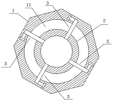
A technology of movable installation and fixed seat, which is applied in the field of lasers, can solve the problems of low efficiency, disassembly and cleaning, inconvenient maintenance, cumbersome installation of fixed structures, etc., and achieve the effect of improved disassembly efficiency, simple and fast installation process, and stable connection structure

Inactive Publication Date: 2015-11-18
JIANGSU ZHUOYUAN LASER TECH
View PDF8 Cites 2 Cited by
  • Summary
  • Abstract
  • Description
  • Claims
  • Application Information

AI Technical Summary

Problems solved by technology

However, such a fixed structure is cumbersome to install, low in efficiency, and inconvenient to disassemble, clean up, and overhaul. Therefore, the present invention develops a structure for the movable installation of the lens holder to realize rapid installation and disassembly of the lens holder.

Method used


Image

  • Movable installation structure of laser lens mounting base
  • Movable installation structure of laser lens mounting base
  • Movable installation structure of laser lens mounting base

Examples


Embodiment 1

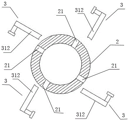
[0021] Such as image 3 As shown, the end of the limiting bar 312 is in a cylindrical structure, and the groove 21 is in a semicircular structure. The end of the cylindrical limiting bar 312 abuts in the semicircular groove 21 .

Embodiment 2

[0023] Such as Figure 4 As shown, the end of the limiting bar 312 is provided with an arc-shaped piece 3121, and the groove 21 is in an arc-shaped structure. The arc-shaped piece 3121 abuts in the arc-shaped groove 21 . The abutment method of the arc structure makes the clipping between the limiting bar 312 and the lens holder 2 more stable.


PUM


Abstract

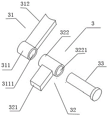
The invention discloses a movable installation structure of a laser lens mounting base, including a lens fine adjustment seat and a lens mounting base. One side of the lens fine adjustment seat is provided with accommodation space. The lens mounting base is installed in the accommodation space and comprises a plurality of connection assemblies. Each connection assembly comprises a spacing piece, a positioning piece and a connection screw rod. Each connection screw rod is sequentially connected with a positioning column on the corresponding positioning piece and a spacing column on the corresponding spacing piece in series by screw threads. The peripheral edge of the lens mounting base is provided with a plurality of grooves. End parts of spacing strips of the spacing pieces abut against the grooves in the lens mounting base in the accommodation space. According to the invention, the whole installation process is simple and rapid, the dismounting can be completed by only unscrewing the connection rod, and the installation and dismounting efficiency is obviously improved.

Description

technical field [0001] The invention relates to a laser, in particular to an installation structure of a lens holder of the laser. Background technique [0002] At present, the lens fixing seat of the laser is installed in the accommodation space of the lens fine-tuning seat, and the lens is installed in the lens fixing seat. However, the lens fixing seat of the laser with this structure is generally fixed in the accommodation space of the lens fine-tuning seat. Some fix the lens fixing seat on the lens fine-tuning seat by screws, and some fix the lens fixing seat by welding Fixed on the lens fine-tuning seat. However, such a fixed structure is cumbersome to install, inefficient, and inconvenient to disassemble, clean up and overhaul. Therefore, the present invention develops a structure in which the lens holder is movably installed to realize quick installation and disassembly of the lens holder. Contents of the invention [0003] Aiming at the shortcomings of the above...

Claims


Application Information

Patent Timeline
IPC IPC(8): H01S3/02
Inventor 万胜文
Owner JIANGSU ZHUOYUAN LASER TECH
Why Eureka
Eureka Blog
Learn More