Powerline communications (PLC) network routing method and system

A technology of power line carrier and communication network, which is applied in distribution line transmission system, wired transmission system, transmission system, etc. It can solve the problem of low communication reliability in the power consumption information collection system, reduce the amount of signaling messages, and reduce loss Packet rate, the effect of improving forwarding efficiency

Inactive Publication Date: 2015-11-18
BEIJING SMARTCHIP MICROELECTRONICS TECH COMPANY +3
View PDF1 Cites 11 Cited by
  • Summary
  • Abstract
  • Description
  • Claims
  • Application Information

AI Technical Summary

Problems solved by technology

[0004] In order to solve the problem of low communication reliability of the power consumption information collection system existing in the prior art, the present invention proposes a power line carrier communication network routing method and system

Method used


Image

  • Powerline communications (PLC) network routing method and system
  • Powerline communications (PLC) network routing method and system
  • Powerline communications (PLC) network routing method and system

Examples


Embodiment 1

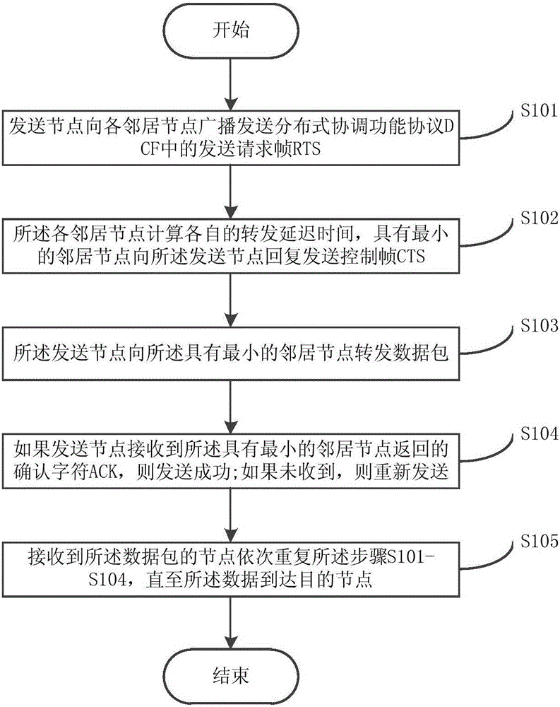
[0031] Such as figure 1 As shown, the power line carrier communication network routing method of the present invention includes:

[0032] Step S101: the sending node broadcasts the sending request frame RTS in the distributed coordination function protocol DCF to each neighboring node;

[0033] The sending node (including the source node or the intermediate forwarding node) broadcasts the RTS frame in the DCF protocol, and waits for the reply of the neighbor node.

[0034] Step S102: each neighbor node calculates its own forwarding delay time T CTS_REQ , with minimum T CTS_REQ The neighbor node of the said sending node replies to send the control frame CTS;

[0035] The node with the minimum forwarding delay time replies the CTS frame to the sending node first, that is, wins the routing competition, and the other neighbor nodes receive the CTS frame sent by the node with the minimum forwarding delay time, cancel their own timers, and give up the routing competition .

[0...

Embodiment 2

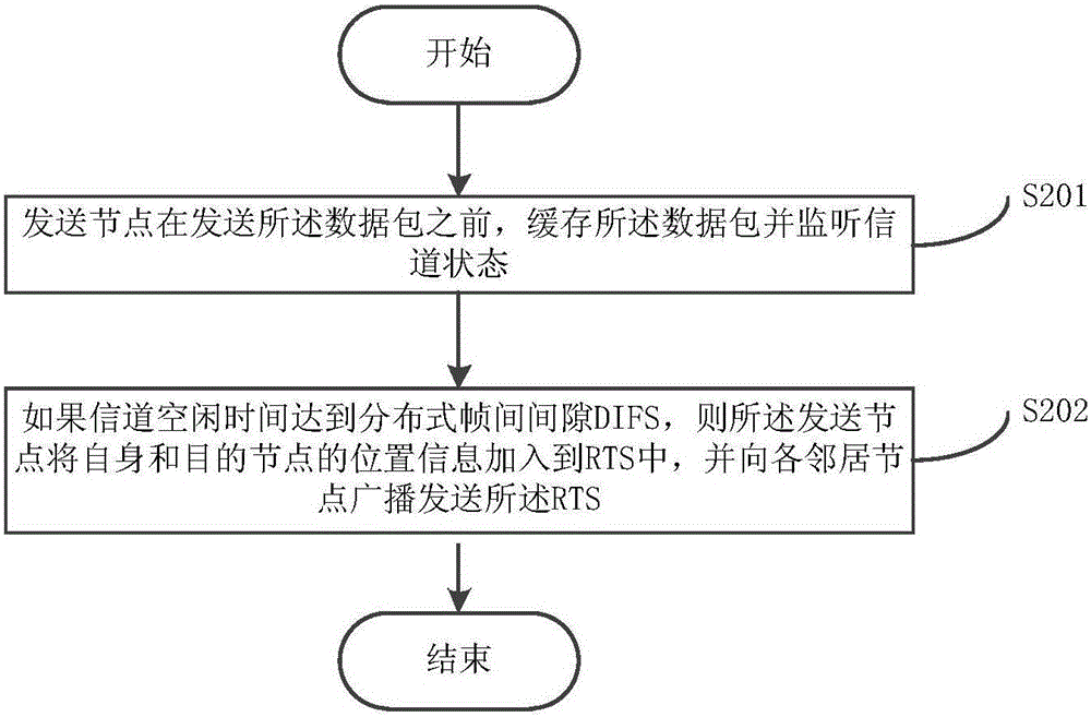
[0046] This embodiment describes the process of step S101 in detail, as figure 2 shown, including:

[0047]Step S201: Before sending the data packet, the sending node buffers the data packet and monitors the channel state;

[0048] Step S202: If the channel idle time reaches the distributed interframe space DIFS, the sending node adds the location information of itself and the destination node into the RTS, and broadcasts the RTS to each neighbor node.

[0049] If the channel idle time reaches DIFS, the sending node puts the location information of itself and the destination node into the header of the RTS frame, and broadcasts it to each neighbor node.

Embodiment 3

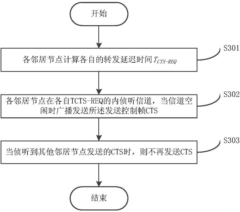
[0051] This embodiment describes the process of step S102 in detail, as image 3 shown, including:

[0052] Step S301: Each neighbor node calculates its own forwarding delay time T CTS_REQ ,

[0053] T C T S _ R E Q = T S I F S + T M A X × P , P = ω 1 × V S N R V S N R _ M A X ...


PUM


Abstract

The invention discloses a powerline communications (PLC) network routing method and system. The method comprises the following steps: step A, a transmitting node transmits a frame of Request To Send (RTS) in a Distributed Coordination Function (DCF) protocol to each neighboring node in a broadcasting manner; step B, each neighboring node calculates own forwarding delay time TCTS_REQ, and the neighboring node having the minimal TCTS_REQ replies to the transmitting node with a frame of Control To Send (CTS); step C, the transmitting node forwards a data packet to the neighboring node having the minimal TCTS_REQ; step D, if the transmitting node receives an acknowledgement character (ACK) returned by the neighboring node having the minimal TCTS_REQ, the transmission is successful; and step E, each node receiving the data packet orderly repeats the steps A to D until the data reaches a target node.

Description

technical field [0001] The present invention relates to the technical field of power communication, in particular to a routing method and system for a power line carrier communication network. Background technique [0002] As a unique communication technology in the power industry, Powerline Communications (PLC) technology has the advantages of wide coverage and low cost, and has been widely used in the field of power user information collection systems. Due to the variability of the power line carrier channel, the topology of the PLC network is often changed and unpredictable, resulting in the establishment and disconnection of links. The routing protocol based on logical topology detects routing lines actively or on demand and saves the corresponding routing table information at each node. However, the application of this routing protocol in a large-scale network environment will cause the problem of control packet broadcast storm. How to find a suitable route in a dynam...

Claims


Application Information

Patent Timeline
Patent Type & Authority Applications(China)
IPC IPC(8): H04L12/727H04B3/54H04L45/121
CPCH04B3/542H04B3/544H04L45/121
Inventor 白晖峰王立城王东山高飞陈静
Owner BEIJING SMARTCHIP MICROELECTRONICS TECH COMPANY
Why Eureka
Try Eureka