Method and device of channel allocation

A channel allocation scheme and channel allocation technology, applied in the field of channel allocation methods and devices, can solve the problems of not being able to take into account concurrent transmission and reserve candidate nodes and eavesdropping opportunities, so as to improve throughput, reduce routing conflicts, and take into account concurrent transmission Effect

Active Publication Date: 2014-10-01
CHINA MOBILE GRP HENAN CO LTD
View PDF3 Cites 8 Cited by
  • Summary
  • Abstract
  • Description
  • Claims
  • Application Information

AI Technical Summary

Problems solved by technology

[0008] The embodiment of the present invention provides a channel allocation method and device to solve the problem that the existing channel allocation scheme cannot take into account concurrent transmission and reserved candidate nodes and eavesdropping opportunities

Method used


Image

  • Method and device of channel allocation
  • Method and device of channel allocation
  • Method and device of channel allocation

Examples


Embodiment 2

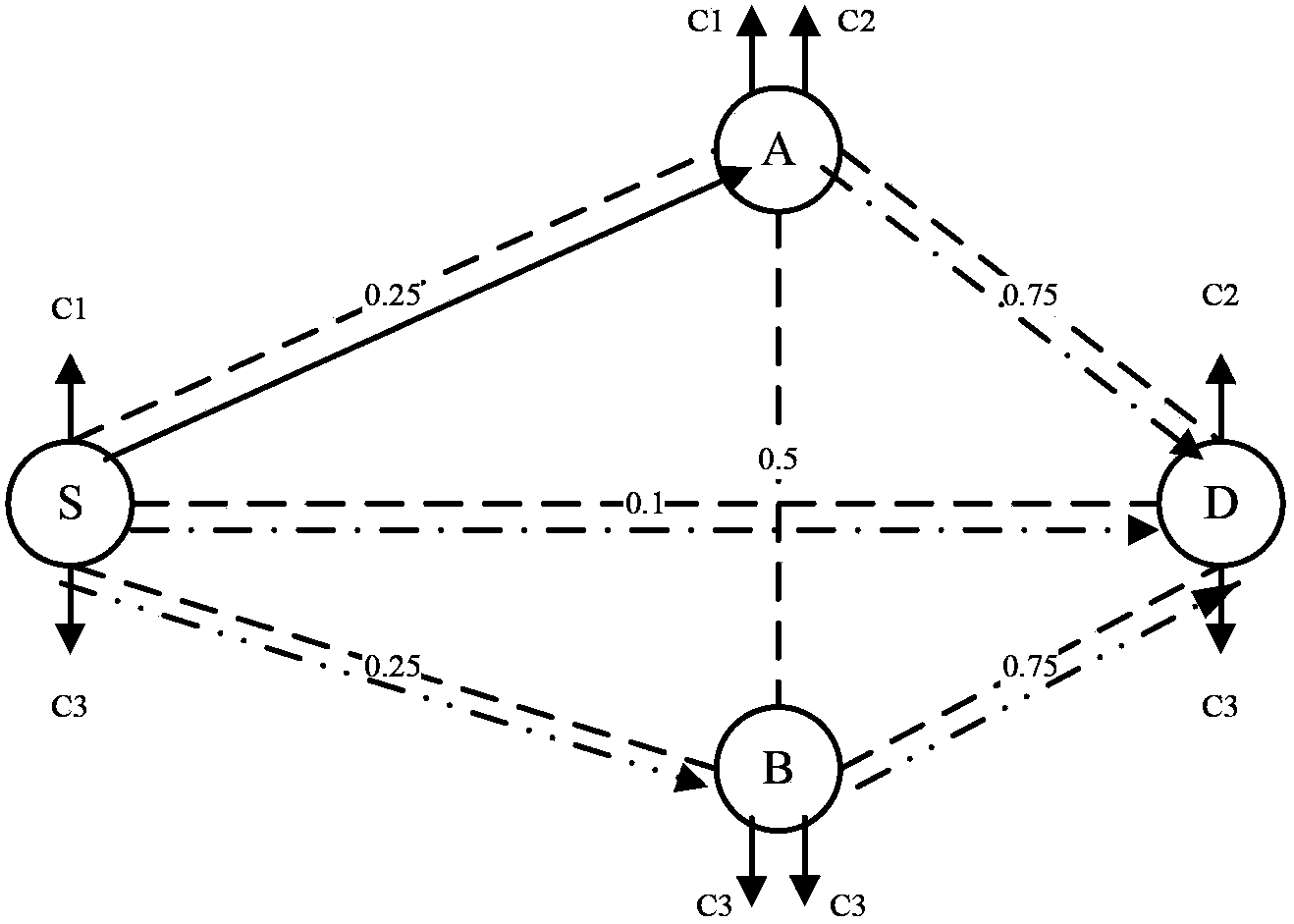
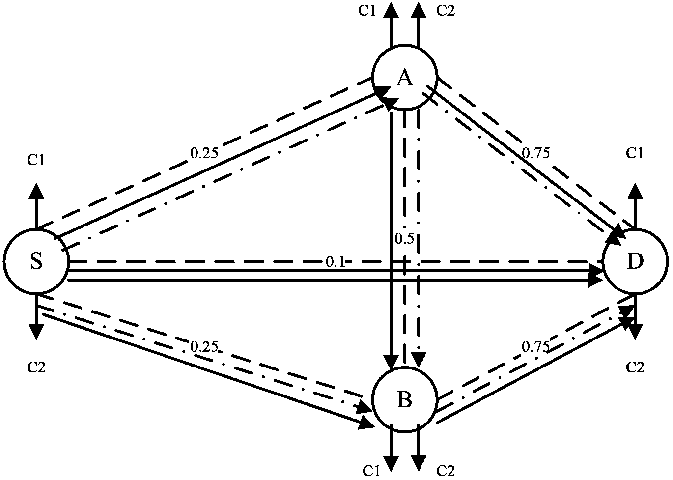
[0119] Such as Figure 9 In the shown wireless mesh network topology diagram, there are 4 nodes and 1 flow, the source node is 1, and the destination node is 4. Each node is configured with 2 wireless radios (R=2), and there are 3 orthogonal channels (K=3) in the network. The numbers on the side indicate the packet delivery rate of the link. Channel allocation needs to be done for all nodes. The specific implementation method is as follows:

[0120] Step 1: Determine the set of candidate nodes.

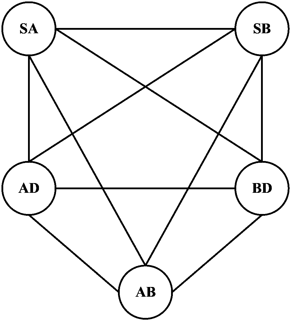
[0121] For source node 1 and destination node 4, the candidate nodes of each node can be obtained by calculating the expected transmission count (ETX) routing criterion, wherein the candidate nodes of node 1 include 2, 3 and 4, and the candidate nodes of node 2 The nodes include 3 and 4, and the candidate nodes of node 3 include 4. Bundle each node with its candidate nodes into a whole as a candidate node set, so that all candidate node sets can be obtained, a total of three cand...

Embodiment 3

[0136] Based on the same inventive concept as that of Embodiment 1 and Embodiment 2, Embodiment 3 of the present invention provides a channel allocation device, such as Figure 10 As shown, the device includes:

[0137] A candidate node set determination module 11, configured to determine a candidate node set corresponding to each node in the wireless mesh network, wherein the candidate node set corresponding to each node includes the node and the node's candidate nodes;

[0138] The channel allocation scheme determination module 12 of the candidate node set is used to determine all feasible channel allocation schemes of the candidate node set according to the channel allocation number constraints of the candidate node set and the radio frequency interface number constraints of each node;

[0139] The channel allocation scheme selection module 13 is used to select a channel allocation scheme from all feasible candidate node set channel allocation schemes, wherein, under the se...


PUM


Abstract

The invention discloses a method and a device of channel allocation. The method is mainly characterized by comprising the following steps of: determining a candidate set of node corresponding to each node in a wireless mesh network, and determining a channel allocation plan for all candidate sets of nodes according to constraint conditions; and selecting one channel allocation plan, wherein the interference of a link between all candidate sets of nodes is minimum under the selected channel allocation plan, and a channel allocated for each candidate set of node of a node serves as the channel allocated for the node. Each candidate set of node serves as a channel allocation unit, and the selected channel allocation plan is a channel allocation plan capable of causing the interference of the link between all candidate sets of nodes to be minimum, and lastly, the channel allocation plan of the node is determined according to the channel allocation plan of the candidate sets of nodes, so that routing conflict between the candidate sets of nodes is reduced through the obtained channel allocation plan of the node, and the multi-channel concurrent transmission is considered while a candidate node and eavesdropping opportunity are reserved, thereby improving the throughput capacity of the channel.

Description

technical field [0001] The present invention relates to the technical field of wireless mesh networks, in particular to a channel allocation method and device. Background technique [0002] Multi-hop wireless network is an extension of Wireless Local Area Networks (WLAN), which can effectively make up for the problems of small WLAN coverage, limited transmission distance, free networking and construction difficulties. It has lower deployment costs and greater coverage. Can provide economical network access service. How to increase the capacity of multi-hop wireless networks through effective technical means, such as routing protocols and channel allocation, has always been a hot area of ​​concern. [0003] Among them, opportunistic routing is an emerging routing method in multi-hop wireless networks. It uses the nature of wireless media broadcasting and multi-user diversity, and does not determine the next hop of the route in advance, and directly broadcasts and sends data ...

Claims


Application Information

Patent Timeline
Patent Type & Authority Applications(China)
IPC IPC(8): H04W16/10H04W40/16
Inventor 曾彬何施茗张大方
Owner CHINA MOBILE GRP HENAN CO LTD
Why Eureka
Try Eureka