Lifting support device and ultrasonic diagnostic apparatus

A supporting device and inner spring technology, which is applied in the direction of sonic diagnosis, infrasonic diagnosis, ultrasonic/sonic/infrasonic diagnosis, etc., can solve the problems of increased operating force, inconvenience, self-locking and other problems of the staff, so as to reduce maintenance costs and expand Scope of application, effect of improving reliability

Active Publication Date: 2015-11-25
SHENZHEN MINDRAY BIO MEDICAL ELECTRONICS CO LTD
View PDF4 Cites 7 Cited by
  • Summary
  • Abstract
  • Description
  • Claims
  • Application Information

AI Technical Summary

Problems solved by technology

[0004] For the lifting structure with self-locking gas spring support control, it can meet the required force value requirements of the balance control panel for a period of time, but most gas springs have the risk of air leakage and force value attenuation. The support structure cannot fully support the control panel equipment, and the operating force of the staff will increase. Sometimes there will be a situation where the force value attenuates greatly, resulting in the inability to support the gravity of the balanced control panel, and the self-locking force will also be significantly weakened due to the large force value attenuation. It cannot be self-locking, so the air spring needs to be replaced, which greatly increases the cost of maintenance and after-sales service; the lifting system adopts an electric control lifting structure, and the screw can provide a large self-locking force, which is not easy to be effective, but there is a control motor inside. It can only be used when the machine is powered on. The motor and the transmission part have a lot of noise during operation, and the cost is high, which brings some inconvenience to the use.

Method used


Image

  • Lifting support device and ultrasonic diagnostic apparatus
  • Lifting support device and ultrasonic diagnostic apparatus
  • Lifting support device and ultrasonic diagnostic apparatus

Examples


Embodiment Construction

[0033] The present invention will be further described in detail below through specific embodiments in conjunction with the accompanying drawings.

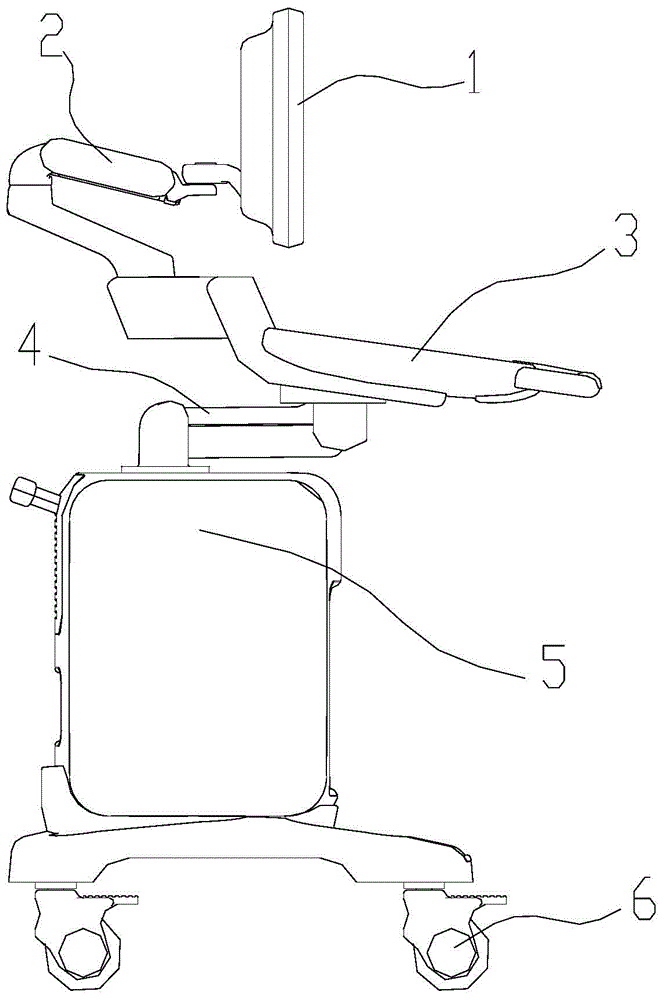
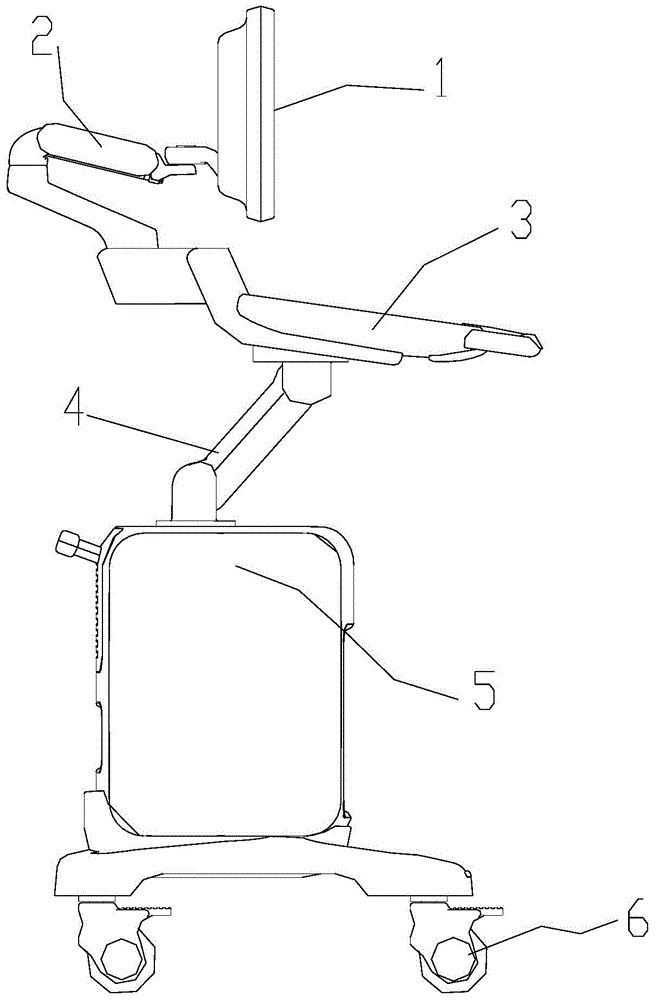
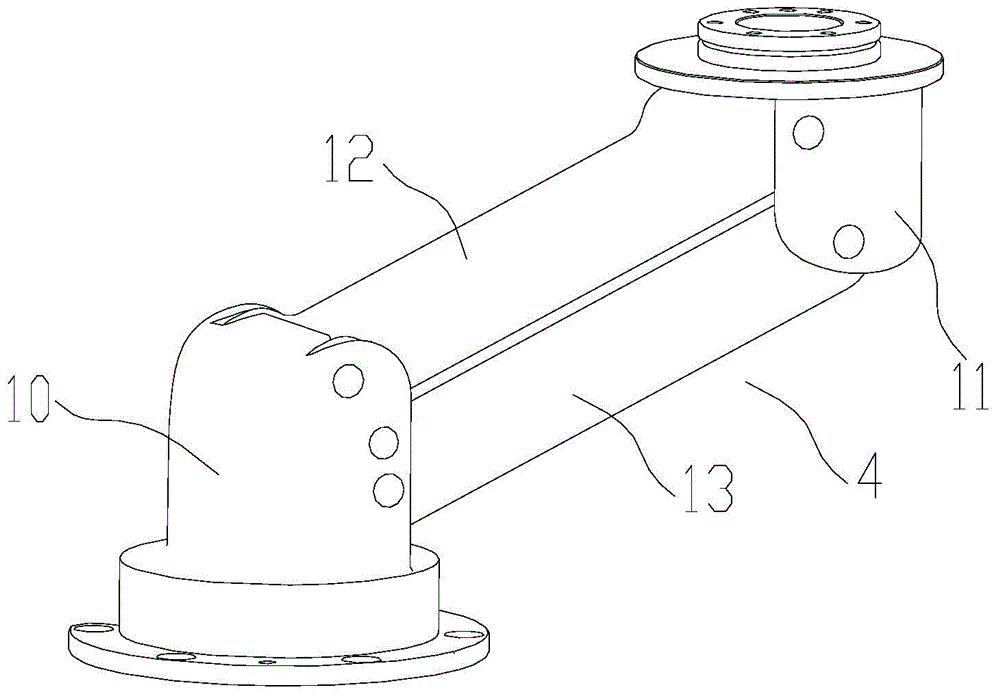
[0034] Such as Figure 3 to Figure 7 As shown, it is the first embodiment of the lifting support device. The lifting support device 4 can support and lift the carrier, which includes a base 10 , an upper bracket 12 and a spring booster 20 . Base 10 is used as the support of the whole device, and one end of upper bracket 12 is connected with base 10 by a rotating pair, so that upper bracket 12 can rotate in a vertical plane relative to base 10, and the other end of upper bracket 12 can support the carrier. The spring booster 20 includes a plurality of springs 27, 28 arranged in the same direction. One end of the spring abuts against the base 10, and the other end of the spring abuts against the upper bracket 12, so that the springs can apply a pushing force or a pulling force to the upper bracket. The moment of tension is used to...


PUM


Abstract

The invention discloses a lifting support device and an ultrasonic diagnostic apparatus. The lifting support device is capable of supporting and lifting a carrier and comprises a base, an upper support and a spring assist; one end of the upper support is rotatably connected with the base, and the other end thereof can support the carrier; the spring assist comprises at least two springs disposed in a same direction; one end of every spring is abutted to the base, and the other end thereof is abutted to the upper support; acting torque that the springs apply to the upper support to balance gravitational torque that the upper support bears. By providing the spring assist with the multiple springs, the acting torque of the springs is used to balance the gravitational torque; since the springs are generally good in stability and rarely fail during long-term using, force values of the springs rarely attenuate, the lifting support device is more reliable, and maintenance cost is lower; owing to the multiple springs, great supporting force can be provided in small space, and applicable range of the lifting support device is widened.

Description

technical field [0001] The present application relates to a lifting support device, in particular to a lifting support device applied in an ultrasonic diagnostic instrument. Background technique [0002] When medical personnel use medical instruments with lifting functions (such as operating the control panel of desktop ultrasound equipment, or operating the display of ultrasound equipment), they often need the control panel or display to be at least within a certain range based on the needs of operation, diagnosis and treatment. For internal lifting, the lifting operation should be light, and it should be able to stop at the required position. At present, the weight of the upper part of the control panel of desktop ultrasound equipment on the market is mostly more than 20 kilograms, which requires a booster mechanism to provide auxiliary support for the control panel to balance the weight of the control panel, so that the medical staff can move the control panel up and down...

Claims


Application Information

Patent Timeline
IPC IPC(8): A61B8/00
Inventor 赵彦群陈志武
Owner SHENZHEN MINDRAY BIO MEDICAL ELECTRONICS CO LTD
Why Eureka
Try Eureka