
A hollow foam shaft and its processing technology

A foam and hollow technology, applied in sports accessories, gymnastics equipment, stilts, etc., can solve the problems of large differences in hardness of surface patterns, shorten the service life of foam shafts, and low utilization of raw materials, achieving short production cycles, low cost, and high utilization high rate effect

Active Publication Date: 2018-05-18
ZHANGJIAGANG HONGLI RUBBER & PLASTIC PROD
View PDF6 Cites 0 Cited by
  • Summary
  • Abstract
  • Description
  • Claims
  • Application Information

AI Technical Summary

Problems solved by technology

[0002] With the continuous improvement of people's living standards, people pay more attention to physical health. Yoga is the preferred item for physical fitness, and foam shafts are ideal auxiliary tools commonly used by yoga practitioners. Most of the foam shafts currently on the market use surface layers. It is a product with patterned EVA material and a plastic hard tube inside that is cut, glued, and molded. , many processes, long production cycle, and low utilization rate of raw materials: the utilization rate of the original board can only reach about 70% through peeling, edge removal, and chamfering during the processing of EVA original board; in addition, although the glue that can meet environmental protection requirements is used, It only shows that the toxicity of the glue is currently within an acceptable range, and it is not 100% environmentally friendly; moreover, the glue seam strength of the EVA material will be lower than that of other parts, which will shorten the service life of the foam shaft; the surface of the finished product is molded The hardness of the pattern varies greatly; since the surface blank of the foam shaft is made of EVA foam material with the same thickness, the pressure on the surface of the product is different due to the depth of the pattern when it is loaded into the shaping mold with the pattern. Hardness is also different (outer hard and inner soft, the difference is 8-10 degrees), and the inner plastic hard tube will be deformed due to high pressure and improper use, shortening the service life, so a better quality, more environmentally friendly and durable tube is needed. foam roller

Method used


Image

  • A hollow foam shaft and its processing technology
  • A hollow foam shaft and its processing technology

Examples


Embodiment 1

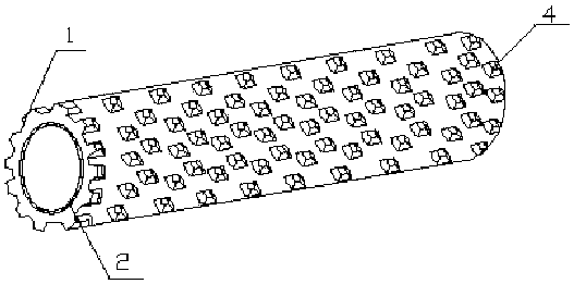
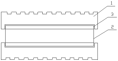
[0035] A hollow foam shaft described in this embodiment includes an outer cladding layer 1 and an inner lining layer 2, the outer cladding layer 1 is a hollow cylinder, a groove 3 is provided inside the outer cladding layer 1, and the inner lining layer 2 is arranged on In the groove 3, the surface of the outer cladding layer 1 is provided with staggered massage bumps 4, the massage bumps 4 are trapezoidal, the shape of the inner lining layer 2 is a hollow cylinder with two ends open, and the inner lining layer The wall thickness of 2 is identical with groove 3 depth.

[0036] The lining layer 2 described in this embodiment is an ABS pipe.

[0037] A method for processing a hollow foam shaft described in this embodiment comprises the following steps:

[0038] (1) Preparation of raw materials: its mass components are: ethylene-vinyl acetate copolymer: 75 parts, N,N′-dinitrosopentamethylenetetramine: 8 parts, urethane and 2-mercaptan Composition of 50% of benzothiazole: 15 par...

Embodiment 2

[0046]A hollow foam shaft described in this embodiment includes an outer cladding layer and an inner lining layer, the outer cladding layer is a hollow cylinder, a groove is provided inside the outer cladding layer, the inner lining layer is arranged in the groove, and the inner lining layer is arranged in the groove. The surface of the outer cladding layer is provided with interlaced massage bumps, the massage bumps are semicircular, the shape of the inner liner is a hollow cylinder with two ends open, and the wall thickness of the inner liner is the same as the depth of the groove.

[0047] The lining layer described in this embodiment is an EVA tube.

[0048] A method for processing a hollow foam shaft described in this embodiment comprises the following steps:

[0049] (1) Preparation of raw materials: its mass components are: ethylene-vinyl acetate copolymer: 70 parts, a composition of 50% of azodicarbonamide and sodium bicarbonate: 10 parts, sulfur monochloride: 12 parts...

Embodiment 3

[0057] A hollow foam shaft described in this embodiment includes an outer cladding layer and an inner lining layer, the outer cladding layer is a hollow cylinder, a groove is provided inside the outer cladding layer, the inner lining layer is arranged in the groove, and the inner lining layer is arranged in the groove. The surface of the outer cladding layer is provided with staggered massage bumps, the massage bumps are in the shape of a wolf tooth, the shape of the inner lining layer is a hollow cylinder with both ends open, and the wall thickness of the inner lining layer is the same as the depth of the groove.

[0058] The lining layer described in this embodiment is an EVA tube.

[0059] A method for processing a hollow foam shaft described in this embodiment comprises the following steps:

[0060] (1) Prepare raw materials: the mass components are: ethylene-vinyl acetate copolymer: 80 parts, 4,4′-oxybisbenzenesulfonyl hydrazide: 5 parts, tetramethylthiuram disulfide: 18 ...


PUM

PropertyMeasurementUnit
particle sizeaaaaaaaaaa
sizeaaaaaaaaaa
sizeaaaaaaaaaa

Abstract

The invention discloses a hollow foam shaft, which comprises an outer cladding layer and an inner lining layer, the outer cladding layer is a hollow cylinder, a groove is arranged inside the outer cladding layer, the inner lining layer is arranged in the groove, and the outer cladding layer The surface is provided with staggered massage bumps, the shape of the inner lining layer is a hollow cylinder with openings at both ends, the wall thickness of the inner lining layer is the same as the depth of the groove, the invention has low cost, fewer procedures and short production cycle. The processing method is scientific, no glue is used, energy saving and environmental protection, the surface material of the produced foam shaft has no splicing, uniform hardness, high strength pattern skin, no cracking, bright appearance, bright color, high rebound rate, durable and no deformation.

Description

technical field [0001] The invention belongs to the technical field of rubber and plastic products, and in particular relates to a hollow foam shaft and a processing technology thereof. Background technique [0002] With the continuous improvement of people's living standards, people pay more attention to physical health. Yoga is the preferred item for physical fitness, and foam shafts are ideal auxiliary tools commonly used by yoga practitioners. Most of the foam shafts currently on the market use surface layers. It is a product with patterned EVA material and a plastic hard tube inside that is cut, glued, and molded. , many processes, long production cycle, and low utilization rate of raw materials: the utilization rate of the original board can only reach about 70% through peeling, edge removal, and chamfering during the processing of EVA original board; in addition, although the glue that can meet environmental protection requirements is used, It only shows that the tox...

Claims


Application Information

Patent Timeline
Patent Type & Authority Patents(China)
IPC IPC(8): A63B26/00C08L23/08C08K13/06C08K9/00C08K3/34C08K5/205C08K5/37C08K3/22C08K5/372C08K3/36C08K3/38C08K5/09C08J9/10C08J9/08
Inventor 章炳芳
Owner ZHANGJIAGANG HONGLI RUBBER & PLASTIC PROD
Learn More