
A two-stage crusher

A crusher and crushing cavity technology, applied in grain processing and other directions, can solve the problems of low output, easy blockage of materials, and the feeding particle size cannot be too large, and achieve the effect of uniform product particle size, not easy to block, and large crushing ratio.

Active Publication Date: 2019-05-03
CHANGSHA SHENXIANG UNIVERSAL MACHINE
View PDF7 Cites 0 Cited by
  • Summary
  • Abstract
  • Description
  • Claims
  • Application Information

AI Technical Summary

Problems solved by technology

The hammer crusher has the characteristics of uniform product particle size, but the disadvantage of the hammer crusher is that the feeding particle size cannot be too large, and the material is easy to block, and the coarse material at the end of the sieve plate cannot be discharged in time; and when the product particle size needs to be obtained Relatively small hours, relatively low output

Method used


Image

  • A two-stage crusher
  • A two-stage crusher
  • A two-stage crusher

Examples


Embodiment 1

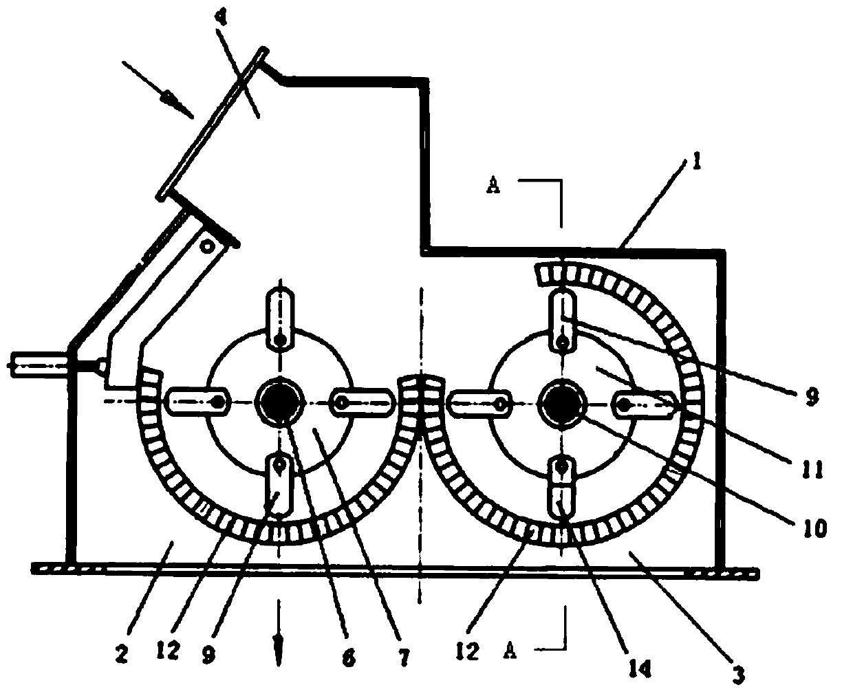
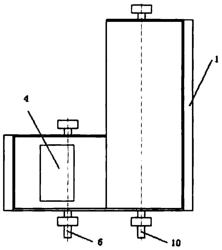
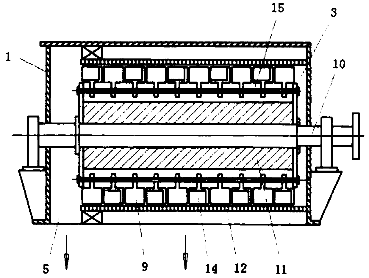
[0035] See attached figure 1 to attach image 3 , with figure 1 to attach image 3 A specific embodiment of a two-stage crusher is provided, wherein, the attached figure 1 For the front view of the double-stage crusher, attached figure 2 It is the top view of the double-stage crusher; image 3 It is the A-A sectional view of the double-stage crusher.

[0036] as attached figure 1 to attach image 3 As shown, the double-stage crusher includes a casing 1. A first crushing chamber 2 and a second crushing chamber 3 are arranged in the casing 1. The first crushing chamber 2 and the second crushing chamber 3 are connected and distributed in the casing 1. On both sides, the first crushing chamber 2 is used to provide a coarse crushing place for materials, and the second crushing chamber 3 is used to provide a fine crushing place for materials.

[0037] The first crushing chamber 2 is provided with a material inlet 4, and the material inlet 4 is used for inputting materials t...

Embodiment 2

[0058] See attached Figure 4 , with Figure 4 Another specific embodiment of the double-stage crusher is provided, wherein, the attached Figure 4 It is the front view of the double-stage crusher.

[0059] as attached Figure 4 As shown, a blow bar 8 is installed on the first rotor 7 , and a hammer head 9 and a material transfer hammer head 14 are installed on the second rotor 11 .

Embodiment 3

[0061] See attached Figure 5 And attached Image 6 , with Figure 5 And attached Image 6 Another embodiment of the double-stage crusher of the present invention is provided, wherein the attached Figure 5 For the front view of the double-stage crusher, attached Image 6 It is a B-B sectional view of the double-stage crusher.

[0062] as attached Figure 5 And attached Image 6 As shown, a blow bar 8 is installed on the first rotor 7 , and a blow bar 8 and a material moving blow bar 13 are installed on the second rotor 11 .


PUM


Abstract

The invention discloses a two-stage crusher. The two-stage crusher comprises a machine shell. A first crushing cavity and a second crushing cavity are formed in the machine shell. The first crushing cavity and the second crushing cavity are communicated and distributed in the two sides of the machine shell. The first crushing cavity is shorter than the second crushing cavity. A feeding inlet is formed in the first crushing cavity. A discharging outlet is formed in the second crushing cavity. A first main shaft is arranged in the first crushing cavity. A first rotor is arranged on the first main shaft. The first rotor is provided with a plate hammer or / and a hammerhead. A second main shaft is arranged in the second crushing cavity. A second rotor is arranged on the second main shaft. A sieve plate is arranged below the second rotor. The second rotor is provided with a plate hammer or / and a hammerhead. At least one of the plate hammer or / and the hammerhead arranged on the second rotor is a material moving plate hammer or / and a material moving hammerhead having an axial material moving function. The two-stage crusher can be used for crushing materials with large granularities and is high in crushing ratio, not prone to blockage and even in product granularity, and products which are high in yield and small in granularity can also be obtained.

Description

technical field [0001] The present invention relates to the field of crushing machinery, and more specifically relates to a double-stage crusher. Background technique [0002] Crusher is a kind of material crushing device, which is widely used in metallurgy, mining, chemical industry, cement and other industries. In many industries, there are a large amount of raw materials and reusable waste that need to be processed by crushers, which need to be crushed to the particle size required by the next step. According to the principle of crushing, crushers can be divided into impact crushers, hammer crushers, jaw crushers, roll crushers, compound crushers and so on. Among them, impact crusher and hammer crusher are two typical crushers. [0003] The impact crusher can also be referred to as impact crusher for short. When the impact crusher crushes materials, driven by the motor, the inner rotor of the impact crusher rotates at a high speed to drive the blow bar on the rotor to r...

Claims


Application Information

Patent Timeline
Patent Type & Authority Patents(China)
IPC IPC(8): B02C13/02B02C13/28
Inventor 郝志刚
Owner CHANGSHA SHENXIANG UNIVERSAL MACHINE
Learn More