Forging equipment with high forging uniformity

A technology of uniformity and equipment, applied in metal processing equipment, manufacturing tools, forging/pressing/hammer devices, etc., can solve the problems of difficulty in the synchronization of the four hammering units, and the inability to guarantee the uniformity of forging. Simple, high synchronicity, improved balance effect

Active Publication Date: 2017-05-31
东莞市驰峰铝业有限公司
View PDF6 Cites 0 Cited by
  • Summary
  • Abstract
  • Description
  • Claims
  • Application Information

AI Technical Summary

Problems solved by technology

[0003] At present, in order to improve the uniformity of forging, it has been increased from the traditional two hammering units to strike against each other to four hammering units, but to ensure the synchronization of two of the hammering units or even all four hammering The synchronization of the units is somewhat difficult, so forging uniformity is still not guaranteed

Method used


Image

  • Forging equipment with high forging uniformity
  • Forging equipment with high forging uniformity
  • Forging equipment with high forging uniformity

Examples


Embodiment 1

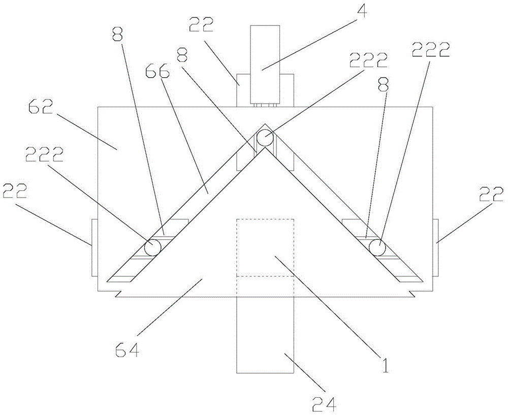
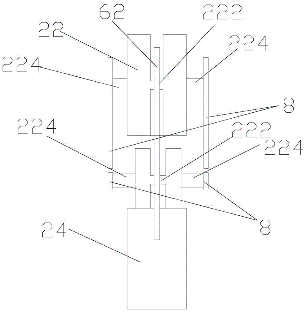
[0021] see Figure 1-2 , a forging equipment with high forging uniformity, including three movable hammering units 22 and one fixed hammering unit 24 distributed in a cross shape, and a driving device 4 for driving each movable hammering unit 22 to move toward the center or outward, Also included are transmissions connecting the drive 4 and the movable hammer unit 22 . The movable hammering unit 22 includes a slider 222, and the transmission device includes two pushers 62, 64 arranged at intervals. The two pushers 62, 64 are block-shaped, forming a gap 66 at a 90° angle between them, and the three sliders 222 can just fit into the gap 66 and one is located at the corner, and the other two are located on both sides of the gap 66. The three movable hammering units 22 are also respectively connected to the limit device, and the driving device 4 can drive the transmission device along the direction of the angle bisector of the corner. reciprocating movement.

[0022] Specificall...

Embodiment 2

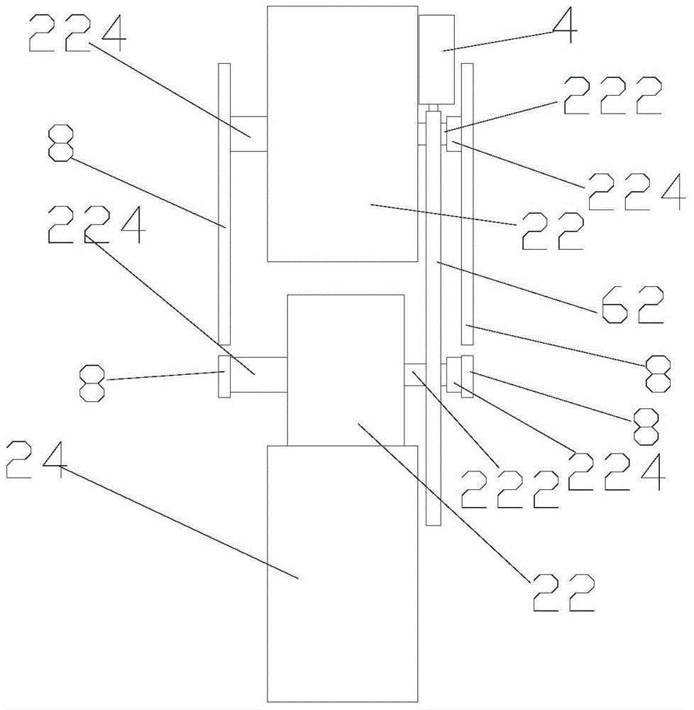
[0028] Such as figure 1 , 3 As shown, a forging equipment with high forging uniformity is different from Embodiment 1 in that the slider 222 is located on one side of the movable hammering unit 22 and inside the corresponding guide block 224 . Since the slider 222 is arranged on the outside of the movable hammer unit 22, the movable hammer unit 22 can be kept in a complete block shape, which is more favorable for hitting and less likely to be damaged.

[0029] The working principle of the present invention is as follows:

[0030] The driving device 4 drives the transmission device downward, and the upper end pusher 62 of the transmission device touches the slider 222 downwards at three corresponding positions respectively, and pushes it downwards, so that the three movable hammering units 22 are restricted by the guide rail 8 All move towards the middle and approach the workpiece 1 until they are hammered on the workpiece 1; conversely, the driving device 4 drives the transm...


PUM


Abstract

The invention relates to a forging device with the high forging uniformity. The forging device comprises three movable hammering units distributed in a crossed shape, a fixed hammering unit and a driving device for driving the movable hammering units to move towards the center or the exterior; the forging device further comprises a transmission device for connecting the driving device with the movable hammering units; each movable hammering unit comprises a sliding block, the transmission device comprises two pushing pieces arranged at intervals, the two pushing pieces are in block shapes, and a gap with a 90-degree corner is formed between the two pushing pieces; the three sliding blocks can right be clamped in the gap, one sliding block is located at the corner, and the two sliding blocks are located on the two sides of the gap; and the driving device can drive the transmission device to perform the reciprocating motion in the direction of the angular bisector of the corner. According to the forging device, the three movable hammering units and the fixed hammering unit are matched so that hitting forging can be carried out on a middle workpiece; the three movable hammering units can be driven to synchronously move through the specially-designed pushing pieces, the structure is simple, the synchronism is high, and therefore the machining uniformity on the workpiece can be greatly improved.

Description

technical field [0001] The invention relates to a forging equipment. Background technique [0002] Forging equipment refers to the mechanical equipment used for forming and separating in forging processing. Forging equipment includes forging hammers for forming, mechanical presses, hydraulic presses, screw presses and flat forging machines, as well as auxiliary equipment such as forging manipulators, uncoilers, straightening machines, and shearing machines. [0003] At present, in order to improve the uniformity of forging, it has been increased from the traditional two hammering units to strike against each other to four hammering units, but to ensure the synchronization of two of the hammering units or even all four hammering The synchronization of the units is somewhat difficult, so forging uniformity is still not guaranteed. Contents of the invention [0004] In order to solve the above technical problems, the object of the present invention is to provide a forging e...

Claims


Application Information

Patent Timeline
Patent Type & Authority Patents(China)
IPC IPC(8): B21J7/14B21J13/00B21J13/04
Inventor 曾衍峰
Owner 东莞市驰峰铝业有限公司
Why Eureka
Try Eureka