Plasma treatment equipment and its electrostatic chuck

An electrostatic chuck and plasma technology, which is applied to circuits, discharge tubes, electrical components, etc., can solve the problem that the second insulating layer, the first insulating layer and the wafer cannot be rapidly heated up, and achieves simple structure and low cost. Low, easy-to-populate effects

Active Publication Date: 2016-03-23
ADVANCED MICRO FAB EQUIP INC CHINA
View PDF6 Cites 0 Cited by
  • Summary
  • Abstract
  • Description
  • Claims
  • Application Information

AI Technical Summary

Problems solved by technology

[0006] However, in the process of heating the wafer by the heater, since the substrate is usually made of aluminum, its thermal conductivity is relatively high, and only silica gel is used to bond the second insulating layer and the substrate, which cannot effectively prevent the second insulating layer from dissipating heat. It is taken away by the cooling liquid in the cooling liquid channel, so that the first insulating layer and the wafer cannot heat up quickly, which affects the process effect of plasma treatment

Method used


Image

  • Plasma treatment equipment and its electrostatic chuck
  • Plasma treatment equipment and its electrostatic chuck
  • Plasma treatment equipment and its electrostatic chuck

Examples


Embodiment Construction

[0018] The specific embodiment of the present invention will be further described in detail below in conjunction with the accompanying drawings.

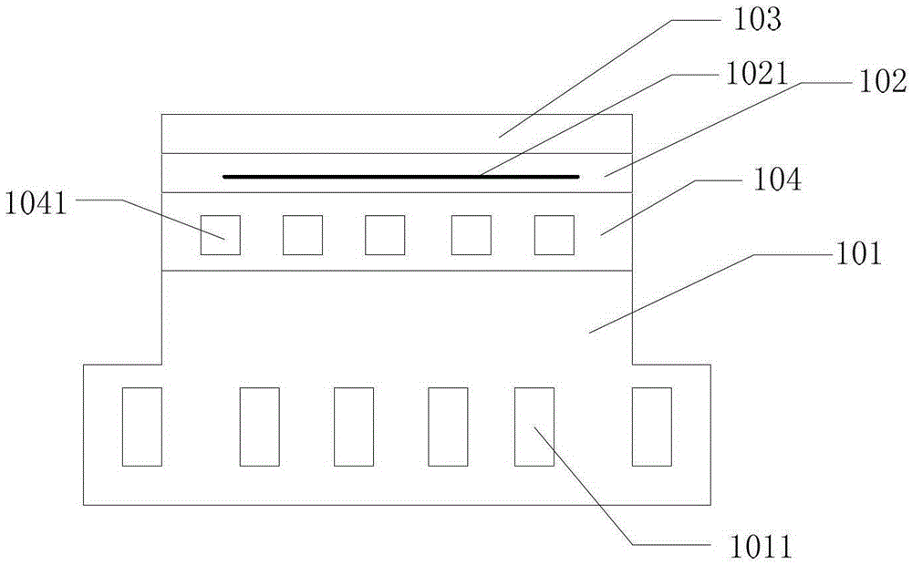
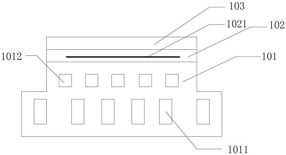
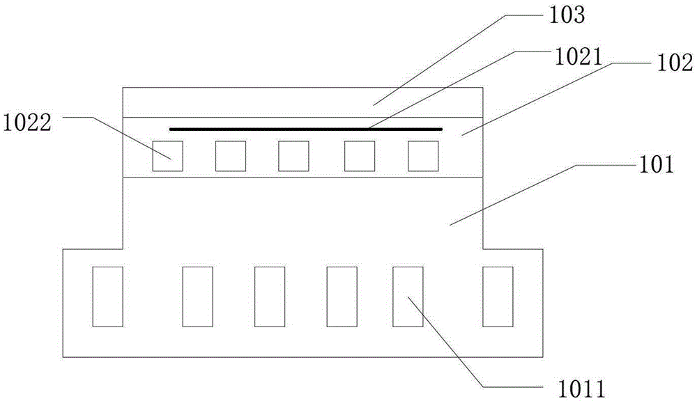
[0019] Such as figure 1 As shown, the first embodiment of the present invention provides an electrostatic chuck, which includes the following parts: a base 101 , a heat insulating layer 104 , a second insulating layer 102 and a first insulating layer 103 , which are layered from bottom to top.

[0020] Specifically, the base body 101 is the bottom of the electrostatic chuck, used to support other parts, and a plurality of coolant flow channels 1011 are arranged inside, used to inject coolant to cool the entire electrostatic chuck; the heat insulation layer 104 serves as a heat insulation unit It is arranged above the base 101 to isolate the heat conduction between the second insulating layer 102 and the base 101; the second insulating layer 102 is arranged above the heat insulating layer 104, and a heater 1021 is arranged inside it ...


PUM


Abstract

The invention relates to a static chuck used in a reaction chamber of a plasma processing device and used for fixing a piece to be machined. The static chuck comprises a first insulating layer, a second insulating layer and a base body and further comprises a thermal insulation unit, wherein the piece to be machined is placed on the first insulating layer, the second insulating layer is located below the first insulating layer, a heater is arranged in the second insulating layer and used for generating heat and heating the piece to be machined through the first insulating layer, the base body is located below the second insulating layer and used for supporting the first insulating layer and the second insulating layer, the base body comprises at least one cooling liquid passageway which is used for injecting cooling liquid to cool the static chuck, and the thermal insulating unit is arranged below the heater and used for lowering the speed at which the heat generated by the heater is taken away by the cooling liquid. According to the static chuck and the plasma processing device, the utilization rate of the heat generated by the heater is improved, and the temperature of the piece to be machined can be rapidly raised.

Description

technical field [0001] The present invention relates to a semiconductor processing technology, more specifically, to a plasma processing device and an electrostatic chuck used in the semiconductor processing technology. Background technique [0002] During processes such as plasma etching or chemical vapor deposition, an electrostatic chuck (ESC for short) is often used to fix, support and transport a wafer (Wafer) waiting to be processed. The electrostatic chuck is installed in the reaction chamber, which uses electrostatic attraction instead of mechanical means to fix the wafer, which can reduce the possible mechanical loss of the wafer, and make the electrostatic chuck and wafer completely contact, which is conducive to heat conduction. [0003] The existing electrostatic chuck generally includes a first insulating layer and a substrate, and a DC electrode is arranged in the first insulating layer, and the DC electrode exerts electrostatic attraction on the wafer. [000...

Claims


Application Information

Patent Timeline
Patent Type & Authority Patents(China)
IPC IPC(8): H01J37/20H01J37/32H01L21/683
Inventor 左涛涛吴狄周宁倪图强王洪青
Owner ADVANCED MICRO FAB EQUIP INC CHINA
Why Eureka
Try Eureka