Combined saw

A compound saw and saw blade technology, applied in the field of cutting devices, can solve problems such as effective protection of saw blades

Active Publication Date: 2015-11-25
杭州民强智能科技有限公司
View PDF10 Cites 6 Cited by
  • Summary
  • Abstract
  • Description
  • Claims
  • Application Information

AI Technical Summary

Problems solved by technology

However, when converting to table saw mode, the table top must be locked in a horizontal position and the part of the saw blade below the table top is a non-working part without exposed teeth, which cannot be formed due to the open guard. Effective protection, so in the table saw mode, an additional protective device or protective mechanism must be added here

Method used


Image

  • Combined saw
  • Combined saw
  • Combined saw

Examples


Embodiment 1

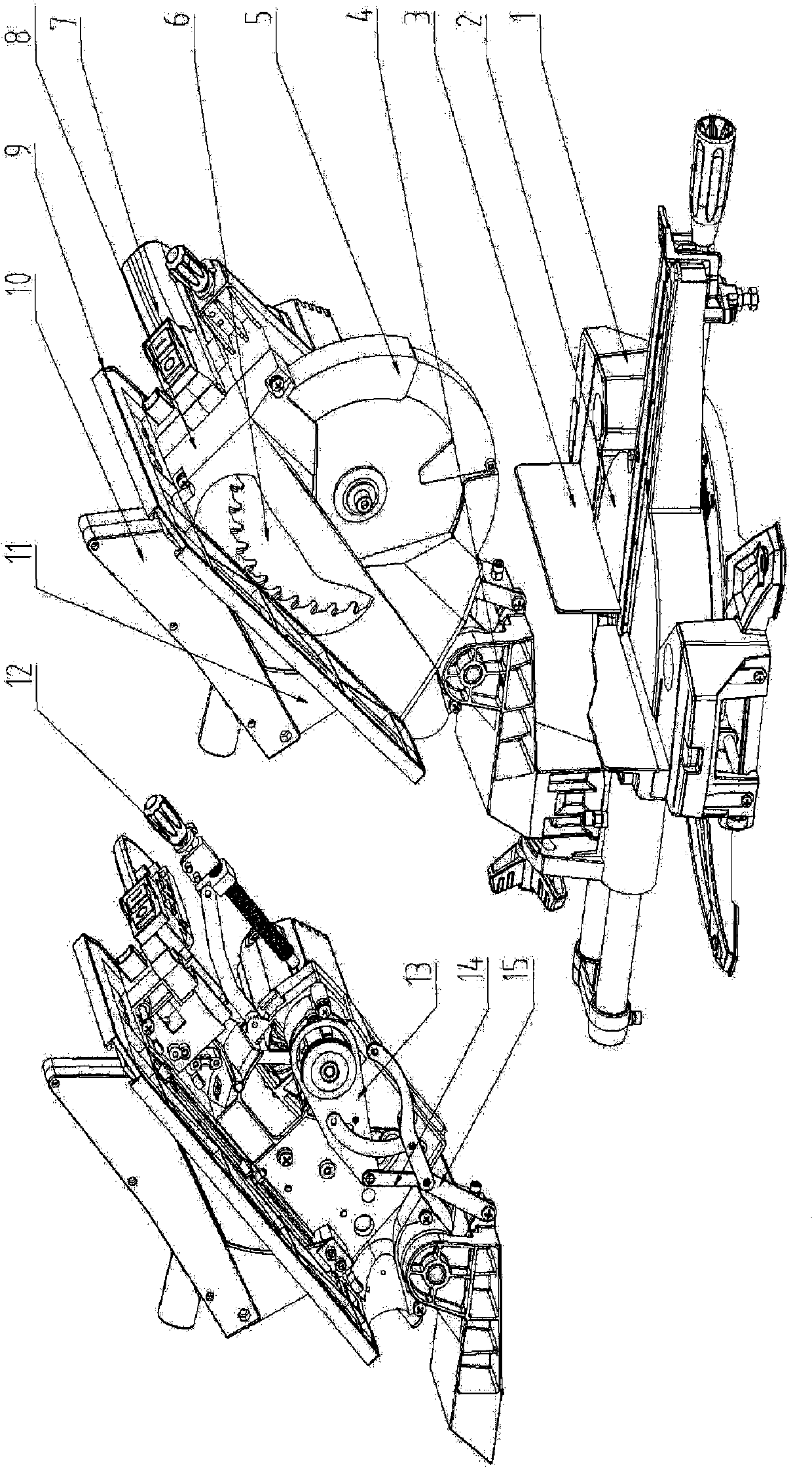
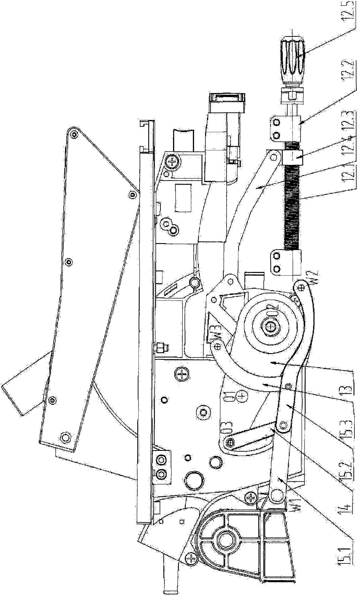
[0038] Such as Figure 2C with 3B As shown, the middle part of the saw blade lifting plate 13 is hinged at the point O1 on the frame, the saw blade (and its power and transmission components) 6 is installed on one end O2 of the saw blade lifting plate 13, and one end of the linkage rod 14 is hinged on the saw blade lifting The other end O3 of the plate 13, and the other end of the linkage rod 14 is hinged with the shield link assembly 15. The shield link assembly 15 is connected with the shield assembly 5 . The protective cover assembly 5 is sleeved on the saw blade (and its power and transmission assembly), and can swing around the same axis as the saw blade under the drive of the protective cover connecting rod assembly. When the saw blade lifting plate 13 swings relative to the frame, one end O2 and the other end O3 of the saw blade lifting plate 13 move in directions opposite to each other.

Embodiment 2

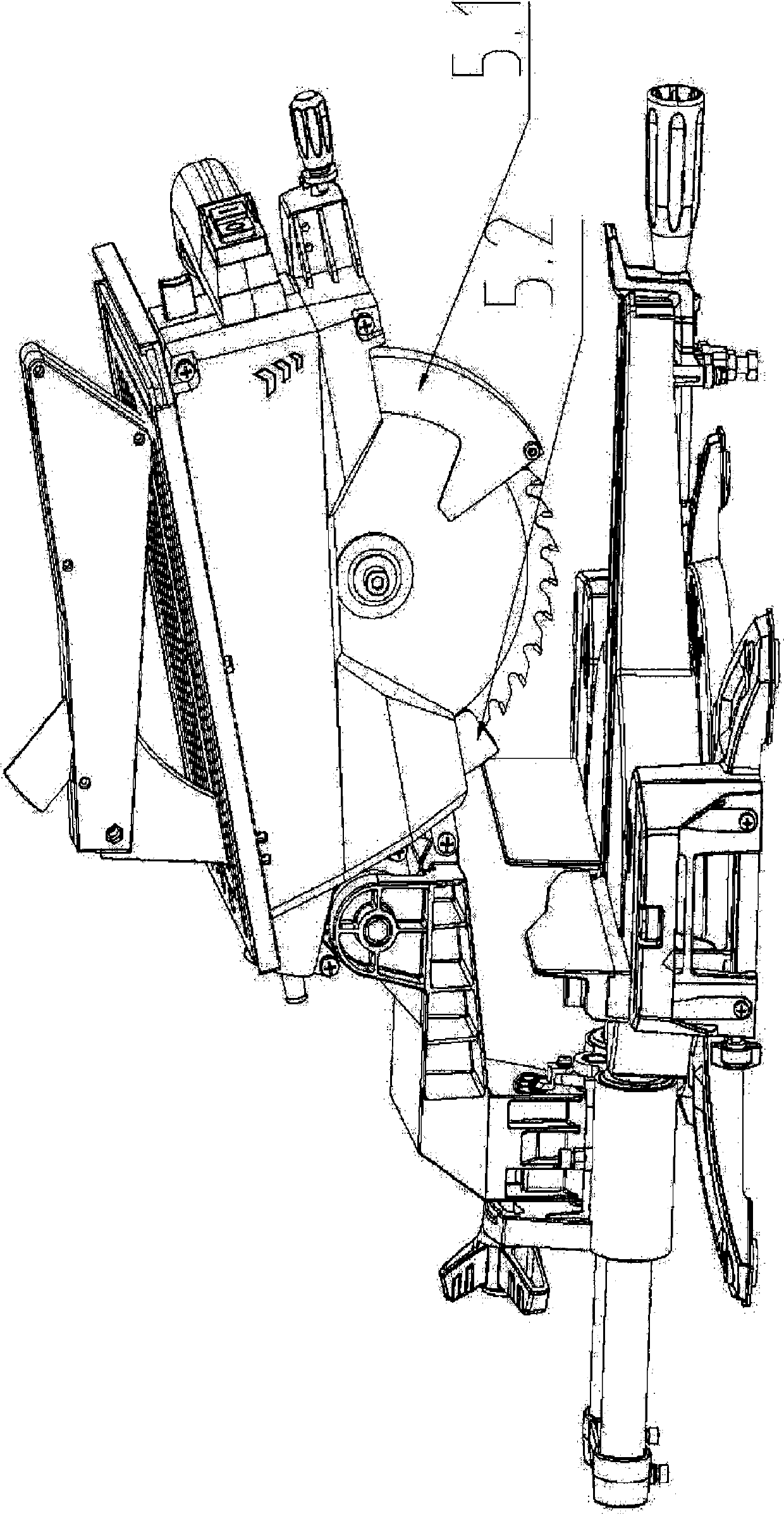
[0040] Such as Figure 5 As shown in A, one end O1 of the saw blade lifting plate 13" is hinged with the frame to become the axis of the saw blade lifting plate swing, and the saw blade (and its power and transmission components) is installed on the other end O2 of the saw blade lifting plate 13". On, one end of linkage rod 14 " is hinged at the point O3 between the points O1 and O2 on the saw blade lifting plate 13 ". The linkage rod 14 " is hinged on the frame by a hinge point O4 in the middle and then at the other end O5 and the shield link assembly 15 hinged, so that when the other end O5 of the linkage rod 14 " hinged with the shield linkage assembly 15 descends The points O2 and O3 on the lifting plate rise simultaneously, and when the other end O5 of the linkage rod and the protective cover link assembly hinged rises, the points O2 and O3 descend simultaneously.

Embodiment 3

[0042] Such as Figure 5 As shown in B, the saw blade lifting plate 13" is fixed on the fixed axis O2 or the fixed guide rail so that the saw blade lifting plate 13" can translate up and down relative to the frame, and the saw blade is installed on the fixed axis O2 or the fixed guide rail of the saw blade lifting plate 13". One end O3 of the linkage rod 14" is hinged on any point on the lifting plate. At this time, the linkage rod 14" is also hinged on the frame through a hinge point O4 in the middle, and then hinged at the other end O5 with the shield linkage assembly 15 , so that when the other end O5 of the linkage rod 14" hinged with the shield link assembly 15 descends, the points O2 and O3 on the lifting plate rise synchronously, and when the other end O5 hinged with the shield linkage assembly of the linkage rod rises, the point O2 and O3 fall synchronously.

[0043] Variation

[0044] Figure 2C The structure of the screw push rod shown is only an exemplary structu...


PUM


Abstract

Disclosed is a compound saw comprising: a frame (8), fixed to a bench panel (9) at its top; a base assembly (1); a working turntable assembly (2); a rocker frame holder (4), which is located between the frame (8) and the working turntable assembly (2) and is hinged to the frame (8) and the working turntable assembly (2), respectively; a saw blade (6), which is used to cut a workpiece; and a saw blade lifting device (12), provided at a lower portion on one side of the frame (8) remote from the hinged end of the frame (8) that is hinged to the rocker frame holder (4), wherein the saw blade (6) is mounted on the saw blade lifting device (12), and the saw blade (6) is able to perform a lifting movement relative to the frame (8), so as to be switched between a bench saw mode, in which the saw blade lifting device (12) lifts the saw blade (6) to an upper portion of the frame (8) such that part of the saw blade (6) is higher than an upper surface of the bench panel (9), and a mitre saw mode, in which the saw blade lifting device (12) lowers the saw blade (6) to the lower portion of the frame (8) such that the entire saw blade (6) is below the upper surface of the bench panel (9).

Description

technical field [0001] The present invention relates generally to cutting devices for cutting workpieces, and more particularly to compound saws capable of switching between a table saw operating mode and a miter saw operating mode. Background technique [0002] In the prior art, a compound saw usually includes a frame 1 ″, a table top 2 ″ arranged on the top of the frame, a saw blade 5 ″ axially fixed on the frame, a base and a working turntable (not shown) below the frame. In the table saw mode, the table top 2” set on the top surface of the frame 1” needs to be placed horizontally. The conversion mode of the working mode of the compound saw is mainly divided into two categories. One is through the relative movement of the table top relative to the frame (including translation and rotation), and the other is by locking and unlocking the table cutting guard. In both cases, the axis of the saw blade is fixed relative to the frame. [0003] Specifically, the overall structur...

Claims


Application Information

Patent Timeline
Patent Type & Authority Applications(China)
IPC IPC(8): B23D47/02B23D47/00B23Q11/06
CPCB23D47/00
Inventor 宋希万
Owner 杭州民强智能科技有限公司
Why Eureka
Try Eureka