
A tiltable rotorcraft and its control method

A technology of a tilting rotorcraft and a control method, which is applied in the field of tilting rotorcraft and its control, can solve the problems of fast horizontal flight speed, long range, and the need for take-off and landing runways, and achieve wide speed range and increased flight envelope. line effect

Active Publication Date: 2017-07-07
IANGSU COLLEGE OF ENG & TECH
View PDF9 Cites 2 Cited by
  • Summary
  • Abstract
  • Description
  • Claims
  • Application Information

AI Technical Summary

Problems solved by technology

The former has a long range and fast horizontal flight speed, but it needs a takeoff and landing runway
The latter does not require a take-off and landing runway, but because its thrust is realized by the horizontal component of the rotor lift, the horizontal speed is not as fast as that of the fixed-wing aircraft, and because its lift is generated by the engine driving the main rotor instead of the airflow passing through Produced by fixed-wing aircraft, so the fuel consumption rate or power consumption for the same flight distance is higher than that of fixed-wing aircraft

Method used


Image

  • A tiltable rotorcraft and its control method
  • A tiltable rotorcraft and its control method
  • A tiltable rotorcraft and its control method

Examples


Embodiment Construction

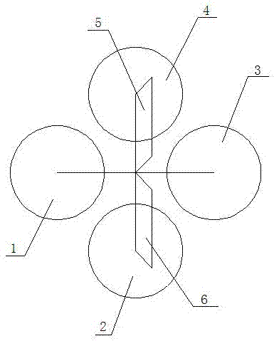
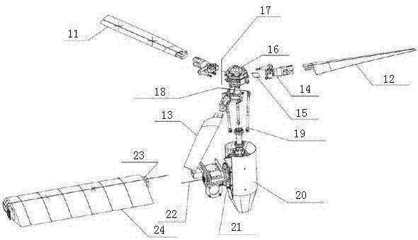
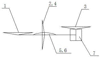
[0020] like figure 1 and figure 2 A tiltable rotorcraft shown includes four sets of tiltable rotors, namely front rotor 1, rear rotor 3, left rotor 2 and right rotor 4, two deflectable wings 5,6, vertical Tail 7, engine, tilting mechanism and pitch-changing mechanism and flight control system, described vertical tail 7, wing 5,6 are connected with described rotor respectively, and described rotor is connected with engine, tilting mechanism and pitch-changing mechanism respectively ;like figure 2 As shown, each set of tiltable rotors includes three blades 11, 12, 13, a hub 16 (including a pitch-variable hinge 14, a shimmy hinge 17, and a flapping hinge 18), a pitch-variable tie rod 19 and a tilting The nacelle 20, each blade is connected to the tilting nacelle 20 through the hub 16 and the variable pitch rod 19, the tilting nacelle 20 is provided with a wing tilting mechanism 21, and the wing tilting mechanism 21 is connected with wing by tilt hinge 22, and described wing ...


PUM


Abstract

The invention discloses a tiltable rotorcraft and a control method thereof. The rotorcraft comprises four sets of tiltable rotors, two deflectable wings, a vertical tail, an engine, a tilting mechanism and a pitch changing mechanism and a flight The control system, the vertical tail and the wings are respectively installed on the fuselage and controlled by the control system. The four groups of rotors are respectively connected with engines, tilting mechanisms and pitch-changing mechanisms; each group of tiltable rotors includes a number of blades, The propeller hub, the pitch variable rod and the tilting nacelle, each blade is connected to the tilting nacelle through the propeller hub and the pitch variable rod respectively, and a tilting mechanism is arranged in the tilting nacelle, and the tilting mechanism Connected to the wing girder through the tilt hinge, the wing has another set of independent deflection mechanism to realize the up and down deflection of the wing. The effect of the invention is that it combines the advantages of the rotorcraft and the fixed-wing aircraft, can take off and land vertically, and can realize long range and fast horizontal flight, increases the flight envelope, and overcomes the respective shortcomings of the two traditional aircrafts.

Description

technical field [0001] The invention belongs to the technical field of unmanned aerial vehicle and its control, and in particular relates to a tiltable rotorcraft and its control method. Background technique [0002] The existing UAVs on the market are mainly divided into two categories: fixed-wing UAVs and rotary-wing UAVs. The former has a long range and fast horizontal flight speed, but it needs a takeoff and landing runway. The latter does not require a take-off and landing runway, but because its thrust is realized by the horizontal component of the rotor lift, the horizontal speed is not as fast as that of the fixed-wing aircraft, and because its lift is generated by the engine driving the main rotor instead of the airflow passing through Fixed-wing generation, so the fuel consumption rate or power consumption for the same flight distance is higher than that of fixed-wing aircraft. Contents of the invention [0003] Purpose of the invention: the purpose of the pres...

Claims


Application Information

Patent Timeline
Patent Type & Authority Patents(China)
IPC IPC(8): B64C27/28B64C27/08
Inventor 连亮
Owner IANGSU COLLEGE OF ENG & TECH
Learn More