
Combination stacker for forklift gearbox transport
A gearbox and combination code technology, which is applied in transportation and packaging, object stacking, storage devices, etc., can solve the problems of easy collision of workpieces, easy collision with pallets, and low transportation efficiency, so as to achieve less space occupation and improve utilization rate, the effect of improving production efficiency
- Summary
- Abstract
- Description
- Claims
- Application Information
AI Technical Summary
Problems solved by technology
Method used
Image

Examples
Embodiment Construction
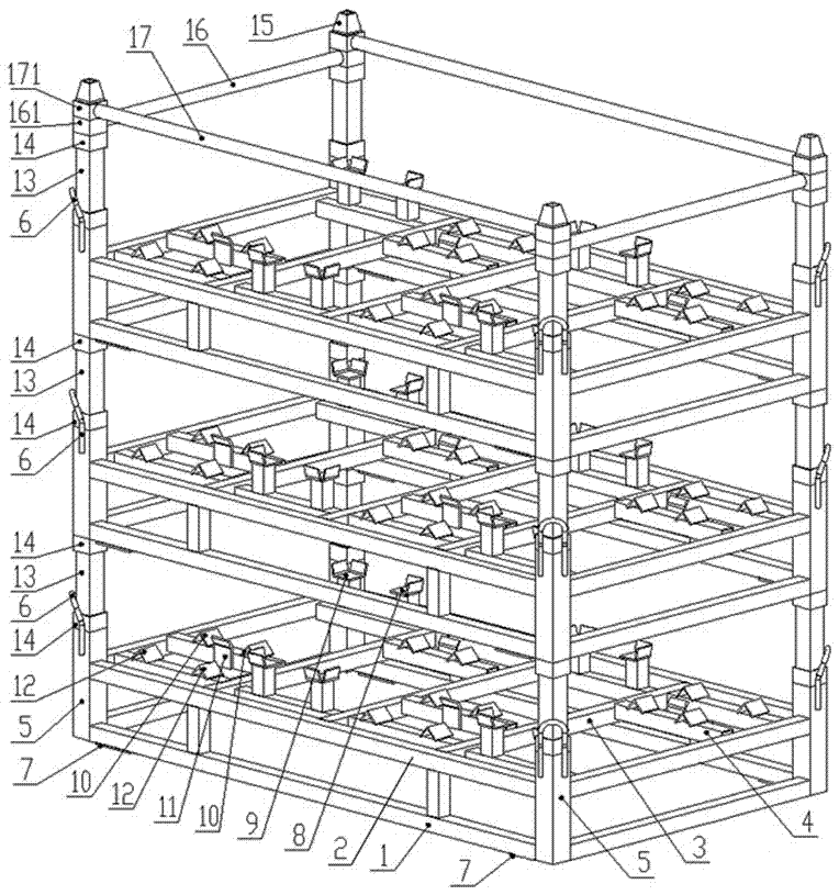
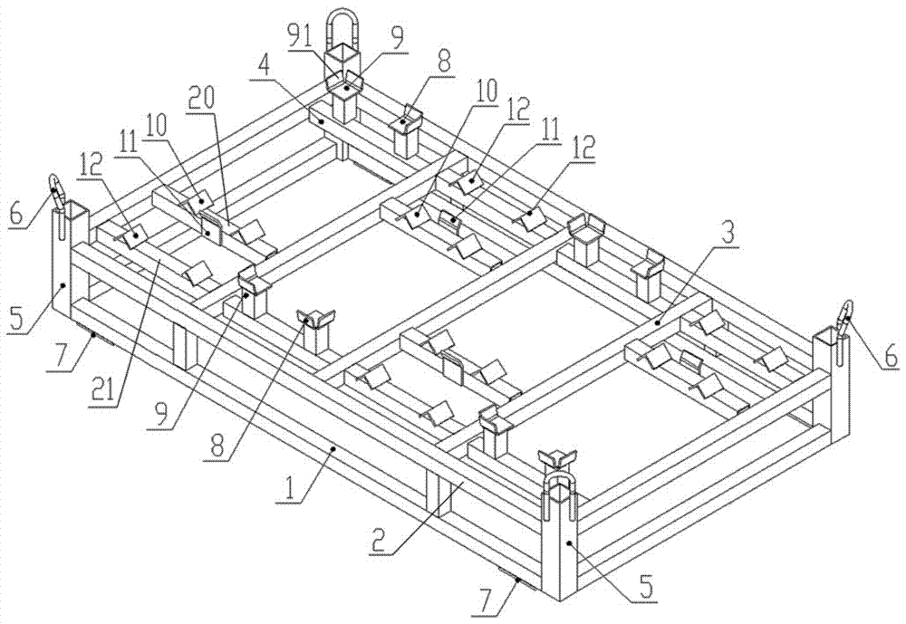
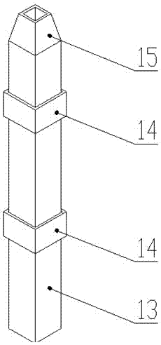
[0035] see figure 1 , combined stacking racks for the transport of forklift gearboxes, including three-tiered transport racks stacked vertically; see figure 2 , the transport frame includes a peripheral main frame 1 and a limiting assembly arranged in the main frame; the main frame 1 is a rectangular frame with upper and lower layers, and the four corners of the lower rectangular frame of the main frame 1 are Vertically arranged intubation tube 5, the two ends of intubation tube 5 are open, and the outer side of intubation tube 5 upper end is vertically connected with the suspension hook 6 that is inverted " U" shape; Both the beam and the two cross beams are fixedly connected to the bottom end of the intubation tube 5, and the ends of the two longitudinal beams of the lower rectangular frame of the main frame 1 are fitted with pads 7;
[0036] Two upper longitudinal beams 2 and two upper beams of the upper rectangular frame of the main frame 1 are all fixedly connected to t...
PUM
 Abstract
Description
Claims
Application Information