An automatic wax removal device for oil wells

An automatic wax removal technology, which is applied in the direction of isolation devices, cleaning tools, boreholes/well parts, etc., can solve the problems of not being able to remove wax quickly and efficiently, and achieve the goals of controlling the running time of the equipment, simplifying the equipment, and improving the life of the equipment Effect

Active Publication Date: 2018-02-02
PETROCHINA CO LTD
View PDF9 Cites 0 Cited by
  • Summary
  • Abstract
  • Description
  • Claims
  • Application Information

AI Technical Summary

Problems solved by technology

[0004] In order to overcome the problem that existing devices cannot remove wax quickly and efficiently, the present invention provides an automatic wax removal device for oil wells. The present invention adopts the shielding property of metal to microwave According to the principle of microwave penetration to organic materials, different types of magnetrons are used according to the type of heating fluid to directly heat the fluid, which can quickly heat the oil well output fluid

Method used


Image

  • An automatic wax removal device for oil wells
  • An automatic wax removal device for oil wells
  • An automatic wax removal device for oil wells

Examples


Embodiment 1

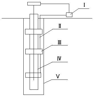
[0021] In order to overcome the problem that the existing devices cannot remove wax quickly and efficiently, the present invention provides an automatic wax removal device for oil wells. The present invention adopts the principle of shielding of microwaves by metals and penetrability of microwaves to organic materials, and according to the type of heating fluid Different, different types of magnetrons are used to directly heat the fluid, which can quickly heat the oil well output fluid. When heating the produced fluid, different types of magnetrons can efficiently heat the produced water and crude oil, and use the upward process of the produced fluid to heat the waxed tubing section. The heated water vapor and associated gas are heated, and the density of the heated water vapor and associated gas becomes smaller, which will form a convective heat exchange with the upper low-temperature gas, which can quickly heat up, compensate for the heat dissipation of the oil pipe, maintain...

Embodiment 2

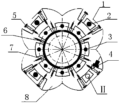
[0031] On the basis of Embodiment 1, in this embodiment, the wax removal unit body 8 is connected to a lotus-shaped platform by four semicircles connected end to end, and the three external magnetrons 2 and one armored The cables II are respectively located at the four semicircular protrusions of the lotus-shaped wax removing unit body 8 .

[0032] Adopt the semicircle material that connects end to end, reduce the weight of wax removal unit body 8 like this, save material, under the situation that guarantees normal operation, save cost, lighten the weight of whole device.

[0033] The outer magnetron 2 and the armored cable II are provided with trapezoidal organic material seals 1 , and the trapezoidal organic material seals 1 are fixed on the wax removal unit body 8 by external fastening bolts 5 .

[0034] An annular organic material seal 7 is arranged in the through hole of the wax removal unit body 8 , and the annular organic material seal 7 and the wax removal unit body 8 ...


PUM


Abstract

The invention provides an automatic wax removal device for an oil well, which includes an oil pipe, and three wax removal units are equidistantly arranged on the oil pipe. The external power distribution cabinet is connected; the wax removal unit includes a wax removal unit body, the middle of the wax removal unit body is a through hole, and a plurality of internal magnetrons are arranged radially along the through hole on the wax removal unit body. Three external magnetrons and an armored cable are evenly distributed on the edge of the wax removal unit body, and a temperature control device is arranged beside the armored cable, and the temperature control device is electrically connected to the wax removal unit. The invention can automatically remove wax without stopping production. When working, when the working temperature of the wax removal unit exceeds the set wax removal temperature by 30°C, the temperature control device will cut off the power and stop heating to protect the safety of the equipment. When the working temperature of the wax removal unit drops to the set wax removal temperature, The temperature control device will automatically connect to the power supply for heating and wax removal.

Description

technical field [0001] The invention belongs to the field of wax removal in oil production wells, in particular to an automatic wax removal device for oil wells. Background technique [0002] In the process of oil field development, it is often accompanied by wax deposition in the oil well. After the tubing is waxed, the fluid production of the oil well will decrease, the number of pump inspections will increase, the load of the pumping unit will increase, and the energy consumption will increase. When the wax deposition is serious, the tubing will be blocked. The oil well does not produce liquid, and when it is more serious, it will cause the sucker rod to break and cause an accident. [0003] At present, paraffin control technology and paraffin removal technology are generally used in paraffin oil wells. Paraffin control technologies include chemical paraffin control and physical paraffin control. Chemical anti-wax is to add anti-wax agent, the cost is high, and the compo...

Claims


Application Information

Patent Timeline
Patent Type & Authority Patents(China)
IPC IPC(8): E21B37/00E21B36/04
Inventor 王小勇杨立华姜毅刘爱华唐泽玮刘宁杨会丽苑慧莹程碧海
Owner PETROCHINA CO LTD
Why Eureka
Try Eureka