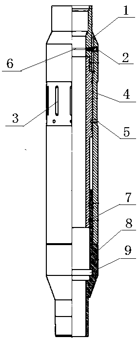
A blasting start sliding sleeve
A sliding sleeve and bursting disc technology, which is applied in the fields of mining fluid, wellbore/well components, and earthwork drilling and production, can solve the problems of difficult construction, long construction period, and high construction cost, so as to avoid perforating operations and improve The effect of construction efficiency and construction cost saving
- Summary
- Abstract
- Description
- Claims
- Application Information
AI Technical Summary
Problems solved by technology
Method used
Image
Examples
Embodiment 1
[0019] This embodiment provides a blasting start sliding sleeve, such as figure 1 As shown, it includes an upper joint 1 and a lower joint 8 connected by threads. There are a plurality of vertical strip-shaped fracturing ports 3 evenly distributed on the pipe wall of the upper joint 1 along the circumferential direction. A piston 4 is installed inside the upper joint 1, and the piston 4 will press the The rupture port 3 is blocked; the upper pipe wall of the upper joint 1 is equipped with a bursting disc holder 2, and the bursting disc holder 2 passes through the pipe wall of the upper joint 1, and the bursting disc holder 2 is located inside the upper joint 1 A bursting disc 6 is installed at one end of the top joint 1, and the bursting disc 6 is in the shape of a disk with the same inner diameter as the upper joint 1, forming a spacer blocking the upper joint 1 in the upper joint 1, and the bursting disc 6 is located at the top of the piston 4.
[0020] In order to ensure a ...
Embodiment 2
[0023] On the basis of Embodiment 1, in this embodiment, the lower end of the piston 4 is located inside the lower joint 8 and the piston 4 and the lower joint 8 are installed in a clearance fit. A circlip groove 9 is provided, and the distance between the circlip 7 and the circlip groove 9 is greater than the distance between the upper end of the piston 4 and the lowermost end of the fracturing port 3 .
[0024] On the basis of the above-mentioned implementation process, when the piston 4 in this embodiment goes down to the bottom of the lower joint 8, the clip spring 7 located outside the lower part of the piston 4 just falls into the clip spring groove 9 at the lower part of the inner wall of the lower joint 8, and passes through the clip. The spring 7 locks the piston 4 in the circlip groove 9 in the lower joint 8 to prevent the piston 4 from going up to block the fracturing port 3 and ensure the smooth progress of the fracturing process.
Embodiment 3
[0026] On the basis of the above two embodiments, this embodiment is further improved and explained. In this embodiment, the piston 4 is placed in the upper joint 1 through clearance fit installation, and the piston 4 is fixed on the upper joint 1 by the shear pin 5. on the inner wall of connector 1.
[0027] Normally, the piston 4 is fixed on the inner wall of the upper joint 1 through the shear pin 5. When the blasting start-up sliding sleeve starts to work, the pipe string is used to pressurize the inside of the casing. When the pressure rises to the predetermined breakdown pressure of the bursting disc, the blasting The sheet is broken down to form a pressure channel, and the liquid pushes the piston 4 downward. Since the piston 4 is fixed on the inner wall of the upper joint 1 at this time, as the pressure rises, the shear force on the shear pin 5 continues to increase until the shear pin 5 When the cutting pin 5 is cut off, the piston 4 starts to descend to complete the ...
PUM
 Abstract
Description
Claims
Application Information
 - R&D
- Intellectual Property
- Life Sciences
- Materials
- Tech Scout
- Unparalleled Data Quality
- Higher Quality Content
- 60% Fewer Hallucinations
Browse by: Latest US Patents, China's latest patents, Technical Efficacy Thesaurus, Application Domain, Technology Topic, Popular Technical Reports.
© 2025 PatSnap. All rights reserved.Legal|Privacy policy|Modern Slavery Act Transparency Statement|Sitemap|About US| Contact US: help@patsnap.com

