Water-proof coiled material layer

A technology of waterproof roll material and laying machine, which is applied to tools used in roofing engineering, roofing, construction, etc. It can solve the problems of harmful gas pollution, damage to human health, and high construction costs, and achieve pollution reduction, labor intensity reduction, and construction quality. Good results

Inactive Publication Date: 2008-01-23
王新格
0 Cites 46 Cited by

AI-Extracted Technical Summary

Problems solved by technology

[0002] At present, most roof waterproofing adopts the laying of new SBS waterproof membrane, which is made of modified asphalt as the base material, and its surface is covered with a layer of aluminum reflective film or sand layer. The surface is sprayed and baked and melted and pasted on the surface of the building. It has the following disadvantage...

Abstract

A waterproof coil laying machine is provided, which pertains to the laying equipment for waterproof coil for waterproof tech in roofs of buildings, and comprises a frame, a laying mechanism and a heater. The laying mechanism comprises a coil shaft 21, guide roll 25 and 28, a tension roll 32, and a pressing roll 33; the heater comprises a mixture gas distribution valve 1, a mixed air conveying pipe 6, and a burner 7. The mixture gas distribution valve 1 is in form of 3 pipe sets. The burner comprises a burner gas pipe 8, a row of flame nozzles 9 mounted on the gas pipe and flame covers 10. The invention realizes mechanization in laying of waterproof coil, is of high construction efficiency, lightens greatly labor intensity; the invention employs LPG, especially compressed air for supporting combustion, the fire is strong, the temperature is high, can enable the surface of the waterproof coil to melt rapidly; and in addition, as the inner course has a low temperature rise, the structure and waterproof property of the whole material will not be damaged, the construction quality is good; as using LPG, the cost is reduced comparing with using gasoline.

Application Domain

Roof tools

Technology Topic

EngineeringGasoline +6

Image

  • Water-proof coiled material layer
  • Water-proof coiled material layer
  • Water-proof coiled material layer

Examples

  • Experimental program(1)

Example Embodiment

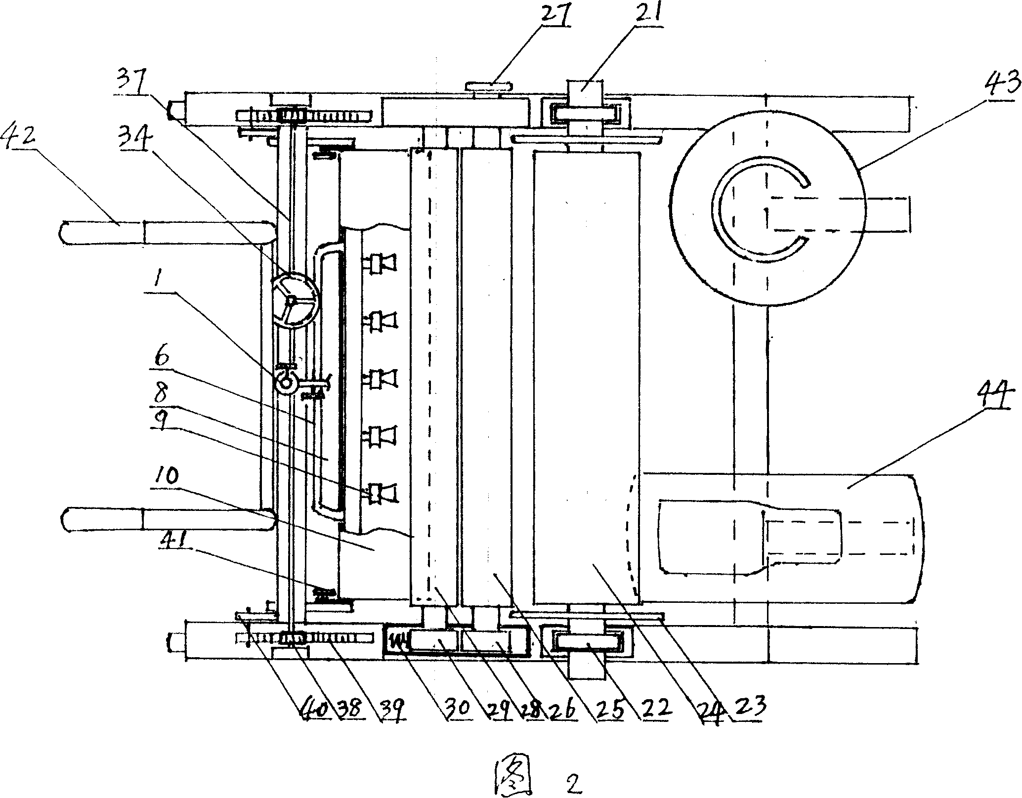
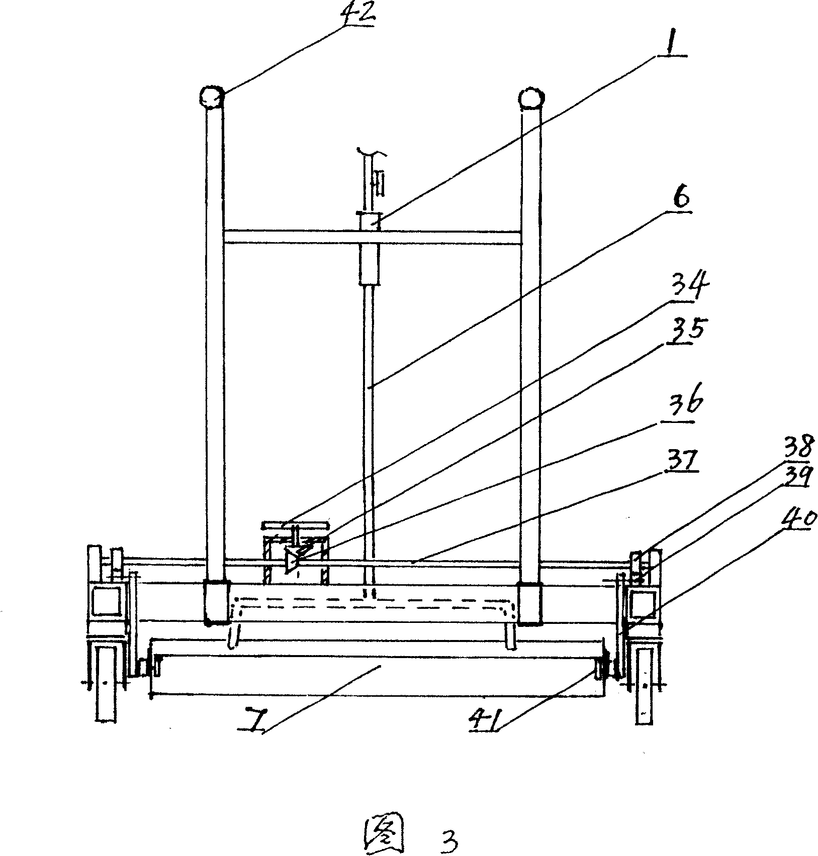
[0014] The basic structure of the present invention can be expressed by accompanying drawing 1 front view of the present invention, accompanying drawing 2 top view of the present invention and accompanying drawing 3 left view of the present invention. There are walking wheels 18 under the frame 19, and the front beam is equipped with handles 42, which can be laid in reverse when laying (the rear handles can also be installed on the rear beam according to the situation, and the front and rear two people can control the construction). Liquefied gas cylinder 43 and air compressor 44 are placed. The laying device is that the coiled material shaft 21 of the set coiled material is placed on the vertical frame 20 in the middle of the frame, the two end bearings of the coiled material shaft are seated in the bearing seats on the vertical frame, and the two ends of the coiled material shaft are respectively equipped with partitions 23, Suit waterproof coiled material 24 between two dividing plates, two dividing plates can prevent coiled material from going off course. A pair of guide rollers 25 and 28 are installed in front of the stand 20, the bearings 26 and 29 at the two ends of the guide rollers are placed in the bearing box 31, and the outer side of one end of the guide roller 25 is equipped with a rotating handle 27, which is used to manually rotate the guide at the beginning of laying Roller, the coil head is introduced between the two guide rollers, the bearing 29 at the two ends of the guide roller 28 has a spring 30 on the bearing box wall, so that the distance between the guide roller 28 and the guide roller 25 is elastically movable, so that there is a gap between the two rollers. With a certain elastic clamping force, the strip-shaped coil is guided between the two guide rollers to the tension roller 32 under the frame, and the tension roller 32 is provided with a pressure roller 33 below it, and the surface of the tension roller will be sprayed with flames after passing through the tension roller. The baked molten coils are pressed against the ground. Above-mentioned adopting a pair of guide rollers 25,28 is the best implementation mode, if only a guide roller is set, or, does not establish guide roller at all, also can implement reluctantly, but its effect will be very poor. The flame heating device is located at the front end of the frame, and it includes a mixed gas distribution valve 1 connected with a liquefied gas cylinder 43 and an air compressor 44, and the mixed gas output by the gas distribution valve is connected to the burner 7 through the gas delivery pipe 6, as shown in Figure 4 Schematic diagram of the structure of the heating device. The gas pipelines 2 and 4 are respectively connected to the liquefied gas tank and the air compressor, and are respectively equipped with adjustment knobs 3 and 5. The mixed gas pipeline 6 is connected to the burner gas pipe 8, and a row of A plurality of flame nozzles 9, the present embodiment establishes 10 flame nozzles, and the flame nozzle adopts an existing liquefied gas combustion nozzle, and the burner 7 is provided with a flame cover 10, and the flame cover two ends are fixed by adjusting the locking handle 41 Installed at the end of the connecting rod 40, the angle of the flame cover can be adjusted according to the needs, so that the flame is sprayed directly on the tension roller and slanted down to the ground, so that the coil can be melted quickly. The burner 7 can move back and forth, and its moving device is composed of a manual handle 34, a bevel gear 35 fixed on the lower end of the handle rod, a bevel gear 36 meshed with it and fixed on the transmission rod 37, and two ends of the transmission rod 37. The toothed gear 38 installed, the toothed rack 39 engaged with it, and the connecting rod 40 connected with the rack constituted. When the handle 34 was turned, it was driven by the conical gears 35 and 36, so that the transmission rod 37 and the two-end toothed gear 38 Rotate, the toothed gear 38 engages the rack 39, the rack moves back and forth, and the burner 7 connected to the end of the connecting rod 40 moves back and forth. Move the burner to the left (toward the front of the rack) for easy ignition, and then move to the right to the spraying position for construction after ignition. The structure of the mixing and distributing valve is formed by the inner pipe 11 with the micropore 12 and the outer pipe 17. The middle casing 14 is added to form a three-tube set. Microholes 12 and 15 are provided on the walls of the inner pipe and the middle casing. Liquefied gas is passed through the core cavity, and compressed air enters the outer pipe and the middle through the pipe 4 and the adjusting knob 5. Between the sleeves, it enters between the inner tube and the middle sleeve through the microhole 15, and then enters the core chamber through the microhole 12 for mixing and distribution. Accompanying drawing 6 has two points difference with accompanying drawing 5, and the one, add a protruding ring 16 on the outer wall of intermediate casing 14, micropore 15, the 2nd, change inner pipe into two-section plug-in form, the plug-in place is set There are air gaps 13 instead of microholes 12. The compressed air needs to be damped by the convex ring first, then enters between the middle casing and the inner pipe through the microholes 15, and then enters the core cavity through the air gaps 13 for mixing. gas. In the above two implementations, the compressed air enters the inner tube core chamber after multiple times of damping and decompression. After that, move the burner in place, and then adjust to the fierce fire construction. Using compressed air to support combustion can make the fire fierce, the flame straight and hard, and the temperature high.
[0015] The working procedure is to load the coiled material first, remove the partition plate 23 with internal thread at one end of the coiled material shaft 21, put the coiled material on it, install the partition plate, drop the bearings 22 at the two ends of the shaft into the bearing seat, and pull the coiled material. The material head is inserted between the two guide rollers 25 and 28, and at the same time, turn the manual knob 27, then the coiled material goes around the tension roller 32 to the pressure roller 33, pulls out (moves to the left) the burner 7, ignites, and advances (Move to the right) When the burner is in place, adjust to high fire and start construction. Hold the handle and go backwards to the left. When laying the first roll, generally the baseline should be drawn first, and the trolley moves along the baseline, and then the trolley can be moved according to the edge of the laid coil as a ruler for subsequent laying.

PUM

no PUM

Description & Claims & Application Information

We can also present the details of the Description, Claims and Application information to help users get a comprehensive understanding of the technical details of the patent, such as background art, summary of invention, brief description of drawings, description of embodiments, and other original content. On the other hand, users can also determine the specific scope of protection of the technology through the list of claims; as well as understand the changes in the life cycle of the technology with the presentation of the patent timeline. Login to view more.

Similar technology patents

Construction method of concrete used for reinforcing underwater pier

Owner:四川路桥建设集团股份有限公司 +1

Classification and recommendation of technical efficacy words

  • Improve construction efficiency
  • Reduce labor intensity

City regional railway signal system and control method thereof

ActiveCN103754242ARun fastReduce labor intensityAutomatic systemsRailway signalEngineering
Owner:CHINA RAILWAY SIYUAN SURVEY & DESIGN GRP
Why Eureka
Try Eureka