

Speed reduction transmission device
A technology of deceleration transmission and sliding sleeve, which is applied in the direction of transmission device, gear transmission device, hoisting device, etc., can solve the problems of coordination transmission error, etc., and achieve the effect of stable limit mechanism, good adaptability and smooth operation process
- Summary
- Abstract
- Description
- Claims
- Application Information
AI Technical Summary
Problems solved by technology
Method used
Image

Examples
Embodiment 1
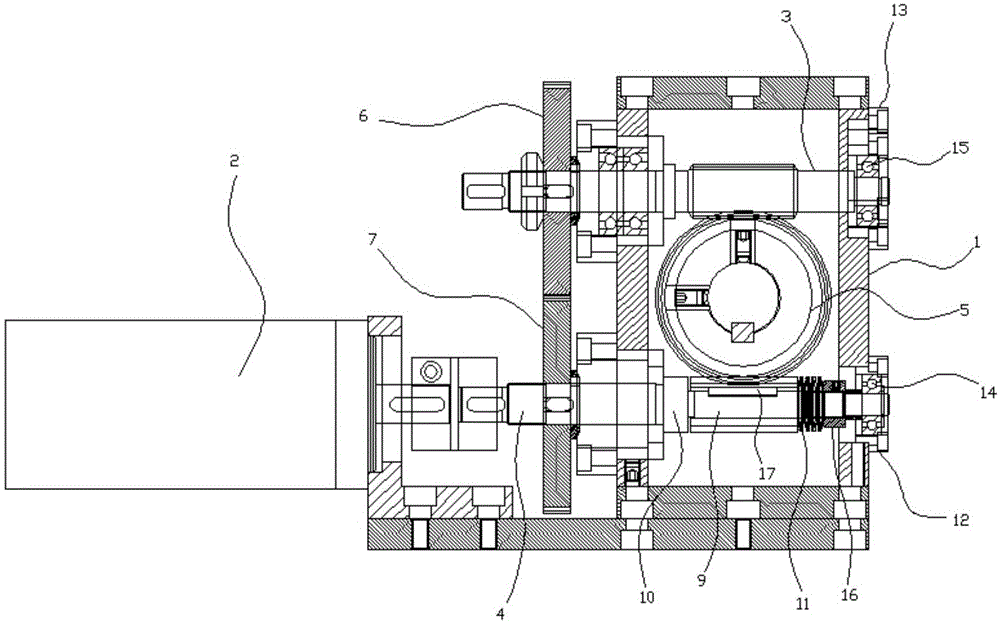
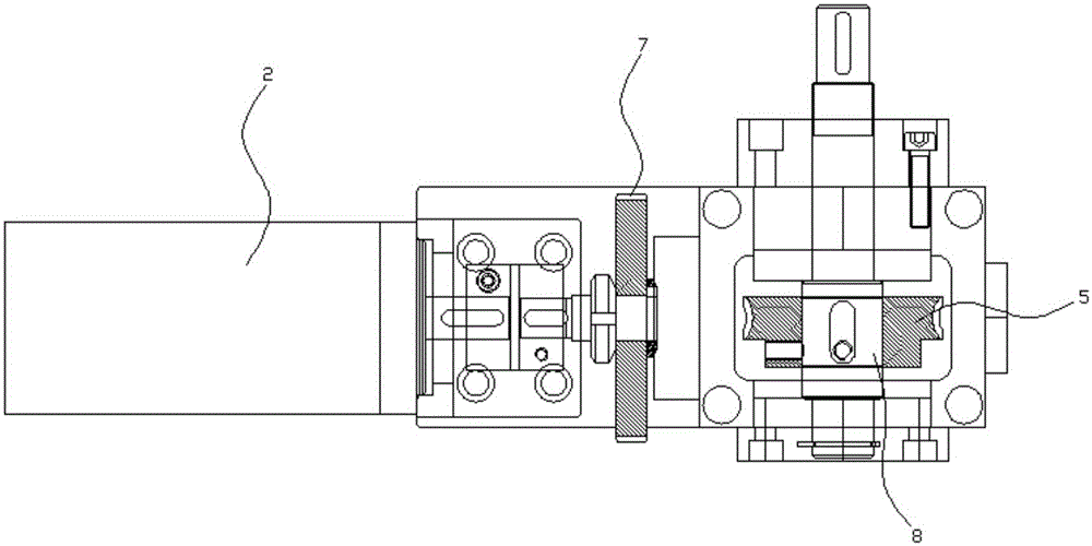
[0022] Embodiment 1: as figure 1 , figure 2 In the shown embodiment, a reduction transmission device includes a box body 1 and a power motor 2, and an upper worm 3, a lower worm 4, and a transmission worm wheel 5 are arranged in the box, and the upper worm and the lower worm All have one end protruding out of the box body, one end of the upper worm sticking out of the box body and one end of the lower worm sticking out of the box body are on the same side of the box body, the upper worm screw and the lower worm screw are respectively provided with upper gears 6, Lower gear 7, the upper gear is coaxial with the upper worm, the lower gear is coaxial with the lower worm, and one end of the lower worm extending out of the casing is connected with the power motor, and the upper worm and the lower worm are connected with the transmission worm gear. Described transmission worm gear is located on a worm gear shaft 8, and described upper gear, lower gear are outside casing, and upper...
Embodiment 2
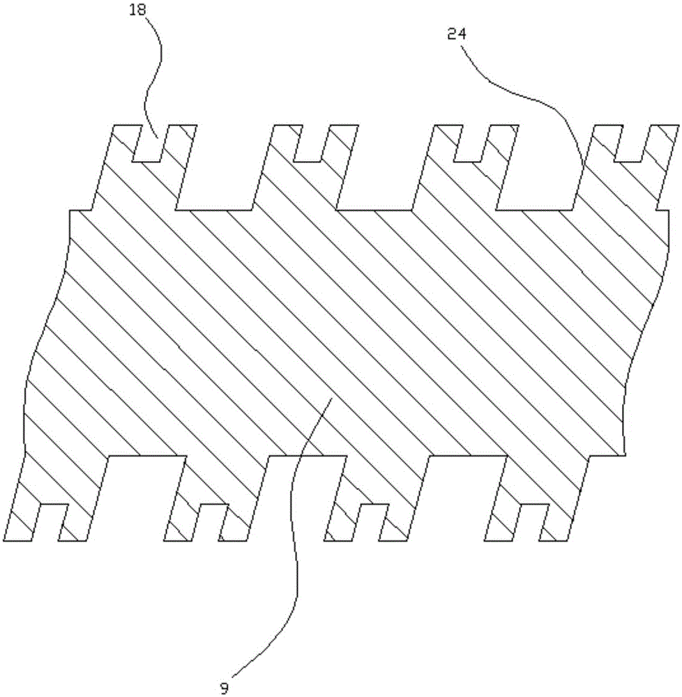
[0028] Embodiment 2: the basic structure and implementation mode of this embodiment are the same as embodiment 1, and its difference is, as image 3 , 4 As shown in , the helical teeth of the lower worm are provided with a continuous helical groove 18 arranged along the helical direction of the helical teeth of the lower worm, and the helical grooves open at the tooth tips of the helical teeth of the lower worm.
[0029] The gear teeth 23 of the transmission worm wheel are provided with a micro-variable elastic channel 19, and the micro-variable elastic channel opens on the tooth top of the gear tooth where it is located, and the gear teeth of the transmission worm wheel are provided with deformation protection holes 20 , the deformation protection hole communicates with the groove bottom of the slightly variable elastic through groove.
[0030] In the previous scheme, with the dynamic adjustment function of the disc spring and the sliding sleeve, the gap can be eliminated to...
Embodiment 3
[0031] Embodiment 3: the basic structure and implementation mode of this embodiment are the same as embodiment 1, and its difference is, as image 3 , Figure 5As shown in , the transmission worm gear includes a worm gear body, several complete teeth 21, and several slotted teeth 22, and the complete teeth and slotted teeth are arranged at intervals on the side edge of the worm gear body in turn, and the slotted teeth are provided with There is a slightly variable elastic through groove, and the slightly variable elastic through groove opens on the tooth top of the gear tooth where it is located; when the complete tooth meshes with the upper worm, the lower worm meshes with the grooved tooth, and when the complete tooth meshes with the lower worm , the upper worm meshes with the grooved teeth. The grooved tooth is provided with a deformation protection hole, and the deformation protection hole communicates with the groove bottom of the slightly variable elastic through groove...
PUM
 Abstract
Description
Claims
Application Information