
A new type of drying cylinder

A drying drum, a new type of technology, applied in drying, drying machine, drying solid materials and other directions, can solve the problems of material adhesion, poor drying effect, easy accumulation of materials, etc., to achieve uniform distribution and improve drying. effect, anti-adhesion effect

Active Publication Date: 2017-09-26
SHANDONG AGRI UNIV FERTILIZER TECH CO LTD
View PDF10 Cites 0 Cited by
  • Summary
  • Abstract
  • Description
  • Claims
  • Application Information

AI Technical Summary

Problems solved by technology

[0003] When the drying cylinder is drying, the material rotates in the drying cylinder. If the material is relatively large and relatively fine, the material is easy to accumulate together, and the drying effect is relatively poor; because the drying is carried out under high temperature conditions, the material may There will be adhesion phenomenon, the existing drying drum can not solve the above problems

Method used


Image

  • A new type of drying cylinder
  • A new type of drying cylinder
  • A new type of drying cylinder

Examples


Embodiment 1

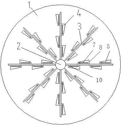
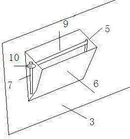
[0030] Such as figure 1 , image 3 As shown, a new type of drying cylinder includes a cylindrical drying cylinder body 1, a rotating shaft 2 is arranged in the drying cylinder body 1 along the axis direction of the drying cylinder, and the center line of the rotating shaft 2 is in line with the drying cylinder. The center line of the cylinder body 1 coincides, and the material plate 3 is fixed on the rotating shaft 2 in a uniform radial direction along the radial extension direction of the rotating shaft. There is no contact, there is a material space between the two, and a material box 4 is arranged on the material plate 3 .

[0031] The magazine 3 includes side plates 5 on both sides, the inner side of the side plate 5 is fixed with the material plate 3, the outer side of the side plate 5 is fixed with an outer plate 6, and the side plate 5, the outer plate 6 and the material plate 3 form an opening 8 material space 9.

[0032] The two side plates 5 of the material box 4 ...

Embodiment 2

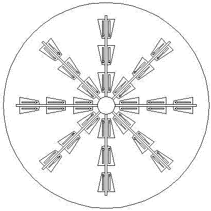
[0035] Such as figure 2 , image 3 As shown, the material box 4 is located on both sides of the material plate 3, the opening 8 of the material box faces the inner wall of the drying cylinder body 1, and the material box 4 is arranged symmetrically. Other technical characteristics are the same as embodiment 1.

Embodiment 3

[0037] Such as Figure 4 , image 3 As shown, the magazines 4 are located on both sides of the material plate 3, the openings 8 of the magazines face the shaft 2, and the magazines 4 are arranged at intervals. Other technical characteristics are the same as embodiment 1.


PUM


Abstract

The invention belongs to the technical field of drying devices, in particular to a novel drying drum. A cylindrical drying drum body is adopted, and a rotating shaft is arranged in the drying drum body along the axial direction of the drying drum, and the center line of the rotating shaft coincides with the center line of the drying drum body, and on the rotating shaft along the direction of the rotating shaft The radial extension direction is uniform and radially fixed with a material plate. The material plate takes the rotating shaft as the center of the circle. The outer end of the material plate does not contact the inner wall of the drying cylinder body. There is a material space between the two. There is a material box on the material plate. The technical solution is that a material plate and a material box are provided in the drum to break up the accumulated materials, lift the materials up and then pick up and unload them, effectively increasing the drying effect.

Description

technical field [0001] The invention belongs to the technical field of drying devices, in particular to a novel drying cylinder. Background technique [0002] As the name suggests, the drying cylinder is the equipment for drying materials. The current drying cylinder has the following problems: [0003] When the drying cylinder is drying, the material rotates in the drying cylinder. If the material is relatively large and relatively fine, the material is easy to accumulate together, and the drying effect is relatively poor; because the drying is carried out under high temperature conditions, the material may There will be a phenomenon of adhesion, and the existing drying cylinder cannot solve the above problems. Contents of the invention [0004] The purpose of the present invention is to provide a new type of drying drum for the deficiencies of the prior art. By providing a material plate and a material box in the drum, the accumulated materials are broken up, and the ma...

Claims


Application Information

Patent Timeline
Patent Type & Authority Patents(China)
IPC IPC(8): F26B11/14F26B25/04
Inventor 马学文马学武丁方军陈士更孟庆羽陈卫民朱军
Owner SHANDONG AGRI UNIV FERTILIZER TECH CO LTD
Learn More