
Sensing device and sensing method

A technology of a sensing device and a sensing method, which is applied in the direction of using an electric/magnetic device to transmit sensing components, etc., can solve the problem of low sensing accuracy of the sensing device, achieve the effect of increasing the change rate and improving the sensing accuracy

Active Publication Date: 2015-11-25
德惠市北方汽车底盘零部件有限公司
View PDF6 Cites 3 Cited by
  • Summary
  • Abstract
  • Description
  • Claims
  • Application Information

AI Technical Summary

Problems solved by technology

However, in this case, the change of the magnetic field intensity is small, and it is difficult to make the magnetic induction element generate the magnetic induction signal in time and accurately, so that the sensing accuracy of the sensing device is not high.

Method used


Image

  • Sensing device and sensing method
  • Sensing device and sensing method
  • Sensing device and sensing method

Examples


Embodiment Construction

[0038] The core of the invention is to provide a sensing device to improve the sensing accuracy of the sensing device. The invention also provides a sensing method.

[0039] In order to enable those skilled in the art to better understand the solution of the present invention, the present invention will be further described in detail below in conjunction with the accompanying drawings and specific embodiments.

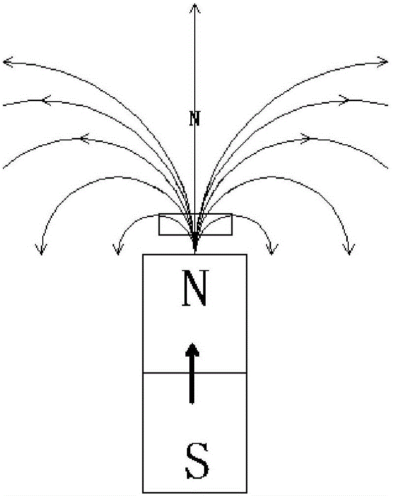
[0040] Please refer to Figure 6 and Figure 7 , Figure 6 It is a schematic structural diagram of the first state of the sensor device provided by the present invention; Figure 7 It is a schematic structural diagram of the second state of the sensing device provided by the present invention.

[0041] In this specific embodiment, the sensing device includes a housing and a bar magnet 1 and a magnetic induction element 2 arranged in the housing. The arrangement direction of the poles moves relative to the magnetic induction element 2; the sensing surface of the ma...


PUM


Abstract

The invention discloses a sensing device and a sensing method. The sensing device comprises a shell, and a bar magnet (1) and a magnetic induction element (2) which are arranged in the shell. The "0" magnetic point mid-position of the bar magnet (1) can move relative to the magnetic induction element (2) along arrangement direction of the N pole and the S pole of the bar magnet (1). The induction surface of the magnetic induction element (2) faces one side, which is parallel to the arrangement direction of the N pole and the S pole of the bar magnet (1), of the bar magnet (1). The moving stroke of the "0" magnetic point mid-position passes through the induction surface of the magnetic induction element (2). The "0" magnetic point mid-position is the position, of which magnetic induction intensity is 0 millitex, of one side along the arrangement direction from the N pole to the S pole of the bar magnet (1). According to the sensing device, rate of change of magnetic field intensity increases so that the magnetic induction element is enabled to generate a magnetic induction signal timely and accurately, and thus sensing accuracy of the sensing device is enhanced.

Description

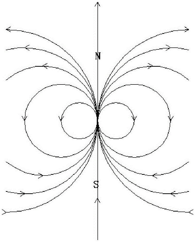
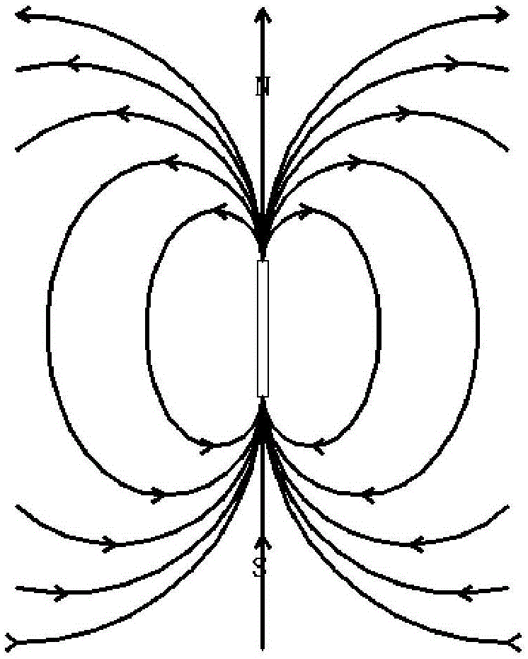
technical field [0001] The invention relates to the technical field of sensing equipment, in particular to a sensing device and a sensing method. Background technique [0002] The magnet itself is a special substance that can cause linear motion in space. But the movement of space leads to the change of space density, and the change of space density makes the space produce diffusion movement. Then the distribution of the magnetic field lines of the external magnetic field of the magnet is generated. Such as figure 1 as shown, figure 1 It is the magnetic force line of a point magnet, but there is no point magnet in real life. And the magnetic field lines of the bar magnet 1 are as follows: figure 2 shown. [0003] The sensing principle of the magnetic induction sensor device is as follows: the relative movement of the magnet and the magnetic induction element makes the magnetic induction element sense the magnetic field lines generated by the magnet and output it as an...

Claims


Application Information

Patent Timeline
Patent Type & Authority Applications(China)
IPC IPC(8): G01D5/12
Inventor 王国强
Owner 德惠市北方汽车底盘零部件有限公司
Learn More