Supercharge Your Innovation With Domain-Expert AI Agents!

A gear early fault detection method

A technology of early failure and detection method, applied in the direction of machine gear/transmission mechanism testing, special data processing applications, instruments, etc., can solve the problems of no established condition monitoring method, lack of analysis, and no proposed rotating machinery condition assessment criteria.

Active Publication Date: 2017-06-20
WEIFANG UNIVERSITY
View PDF2 Cites 0 Cited by
  • Summary
  • Abstract
  • Description
  • Claims
  • Application Information

AI Technical Summary

Problems solved by technology

However, the above methods generally lack the analysis of the dynamic development process of rotating machinery faults, no corresponding evaluation criteria for the state of rotating machinery have been proposed, and no feasible state monitoring methods have been established.

Method used


Image

  • A gear early fault detection method
  • A gear early fault detection method
  • A gear early fault detection method

Examples


Embodiment example 1

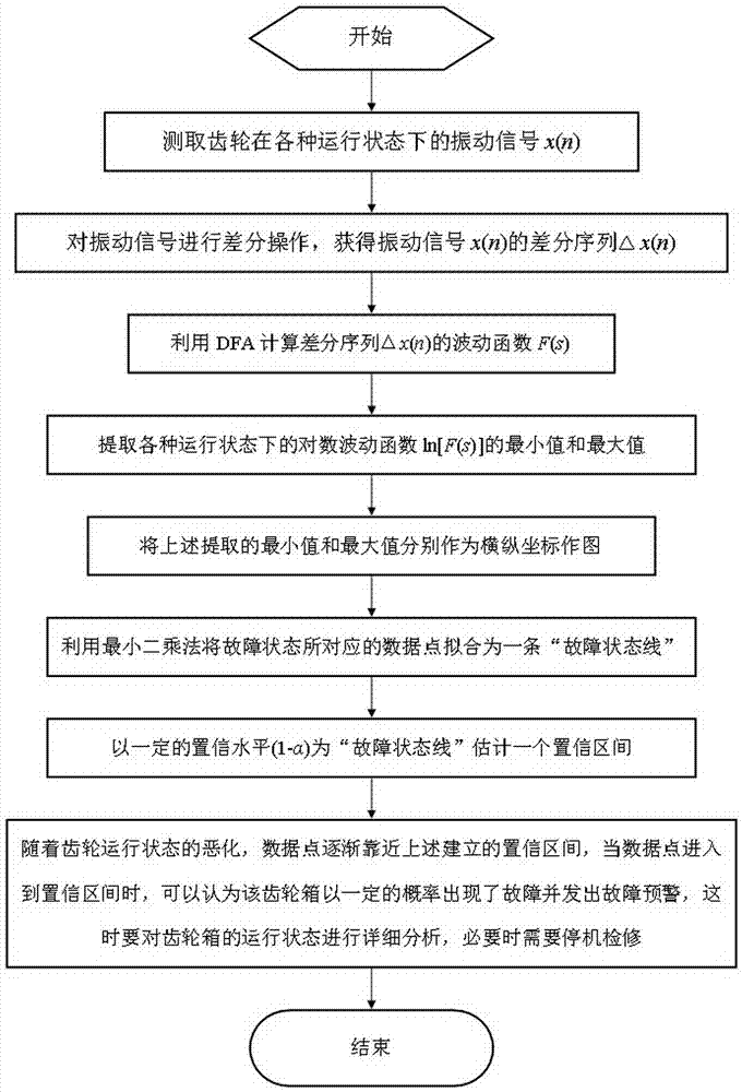
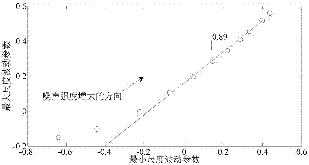
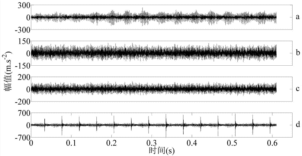
[0038] The practicability of the method of the present invention is verified by using the gear failure data measured from the gearbox test bench. The tooth numbers of the active and passive gears of the gearbox are 24 and 29 respectively, the rotational speed of the active gear is 1420RPM, and the sampling frequency is 16384Hz. Slight wear, moderate wear and broken tooth faults were simulated on the gearbox respectively. Utilize the method described in the present invention to analyze the gear box vibration signal under normal state and above-mentioned three kinds of failure states, the result is as follows Figure 4 shown. From Figure 4 It can be seen that the data points corresponding to the three fault states can be approximately fitted as a "fault state line", while the data points corresponding to the normal state obviously deviate from this straight line. In addition, since the operating state of the gear has a close relationship with the signal-to-noise ratio, gener...

Embodiment example 2

[0040] Gear faults of different severity are manufactured on the experimental gearbox to simulate the evolution process of gear faults. The practicability of the method of the present invention is verified by using the gear fault data collected. The number of teeth of the active and passive gears of the gearbox is 25 and 40 respectively, and a fault is produced on the active gear, and the rotational speed of the active gear is 1600RPM. Slightly scratched, moderately scratched and severely scratched faults were simulated on the gear. Utilize the method described in the present invention to analyze the gear vibration signal under normal state and above-mentioned three kinds of failure states, the result is as follows Figure 6 shown. From Figure 6 It can be seen that the data points corresponding to the three fault states can be approximately fitted as a "fault state line", while the data points corresponding to the normal state obviously deviate from this straight line. In...


PUM


Abstract

A vibration signal x(n) of a gear under each operation state is measured and obtained. A difference sequence delta x(n) of the vibration signal x(n) is obtained by performing a difference operation on the vibration signal. A fluctuation function F(s) of the difference sequence delta x(n) is calculated by using Detrended Fluctuation Analysis (DFA). The minimum value and the maximum value of a logarithmic fluctuation function ln[F(s)] at each operation state are extracted. A picture is drawn by respectively taking the extracted minimum value and maximum value as a horizontal coordinate and a vertical coordinate, and data points corresponding to the fault states are fitted into a ''fault state line'' by using a least square method. A confidence interval is estimated for the ''fault state line'' by using a certain confidence level (1-alpha). Along with the deterioration of gear operation states, the data points are gradually close to the established confidence interval. When the data points are in the confidence interval, it may be considered that a gear box has fault in a certain probability and the fault early warning is sent out, at this time the operation state of the gear box is analyzed detailedly, and if necessary, the shutdown maintenance is needed.

Description

technical field [0001] The invention relates to the field of state monitoring and fault diagnosis of rotating machinery, in particular to a gear early fault detection method. Background technique [0002] Gear is one of the key components of rotating machinery and has been widely used in industrial production. Its operating conditions not only affect its own operation, but also have a direct impact on related mechanical equipment. If the gear fails, it will affect the normal operation of mechanical equipment, and it will cause major economic losses, and even crash accidents and casualties. If during the operation of gears, people can use fault diagnosis technology to find potential hidden troubles in time and deal with them effectively, then not only can the safe operation of mechanical equipment be effectively guaranteed, but also major accidents can be avoided. Therefore, strengthening the research on gear early fault detection and diagnosis technology has important theor...

Claims


Application Information

Patent Timeline
IPC IPC(8): G01M13/02G06F19/00
Inventor 林近山窦春红
Owner WEIFANG UNIVERSITY
Features
  • R&D
  • Intellectual Property
  • Life Sciences
  • Materials
  • Tech Scout
  • Unparalleled Data Quality
  • Higher Quality Content
  • 60% Fewer Hallucinations
Learn More