Method for measuring internal resistance of marine Ag/AgCl electric field sensor
A technology of electric field sensor and measurement method, which is applied to measurement devices, measurement of electrical variables, measurement of resistance/reactance/impedance, etc., can solve the problem that it is difficult to appear semi-circular patterns in impedance complex plane diagrams, and achieves simple and fast measurement methods and measurement results. Accurate, damage-reducing effects
- Summary
- Abstract
- Description
- Claims
- Application Information
AI Technical Summary
Problems solved by technology
Method used
Image
Examples
Embodiment 1
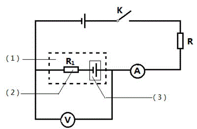
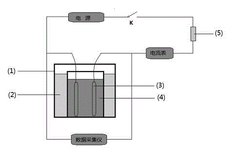
[0031] A pair of Ag / AgCl electric field sensors prepared by electrolysis were placed close together in a 3.5% NaCl solution, and then placed in a thermostat at 20 °C for 3 days. After the temperature of the solution is stable and the range of the electric field sensor is stable, the electric field sensor, data acquisition instrument, ammeter, DC power supply, and resistance box are figure 1The connection method is connected to the circuit. The output voltage of the DC power supply is set to 0.1V, and the resistance value of the resistance box is set to a maximum value of 20KΩ. switch K is open, the measured V 1 =0.036mV, close the switch K, read the voltage value V of the data acquisition instrument quickly after the current is stable 2 =0.040mV, ammeter reading A=0.63μA, according to the formula R=U / I=|(V 2 -V 1 ) / A| Calculated resistance R=6.35Ω. Cut off the power supply, and record the time for the voltage value of the data acquisition instrument to drop from 0.04mV to...
Embodiment 2
[0036] A pair of Ag / AgCl electric field sensors prepared by electrolysis were placed close together in a 3.5% NaCl solution, and then placed in a thermostat at 20 °C for 3 days. After the temperature of the solution is stable and the range of the electric field sensor is stable, the electric field sensor, data acquisition instrument, ammeter, DC power supply, and resistance box are figure 1 The connection method is connected to the circuit. The output voltage of the DC power supply is set to 0.1V, and the resistance value of the resistance box is set to 20KΩ. switch K is open, the measured V 1 =0.035mV, close the switch K, read the voltage value V of the data acquisition instrument quickly after the current is stable 2 =0.039mV, ammeter reading A=0.63μA, according to the formula R=U / I=|(V 2 -V 1 ) / A| Calculated resistance R=6.35Ω. Cut off the power supply, and record the time for the voltage value of the data acquisition instrument to drop from 0.039mV to 0.035mV at the s...
Embodiment 3
[0041] A pair of Ag / AgCl electric field sensors prepared by electrolysis were placed close together in a 3.5% NaCl solution, and then placed in a thermostat at 20 °C for 3 days. After the temperature of the solution is stable and the range of the electric field sensor is stable, the electric field sensor, data acquisition instrument, ammeter, DC power supply, and resistance box are figure 1 The connection method is connected to the circuit. The output voltage of the DC power supply is set to 0.5V, and the resistance value of the resistance box is set to 20KΩ. switch K is open, the measured V 1 =0.031mV, close the switch K, read the voltage value V of the data acquisition instrument quickly after the current is stable (about 3 seconds) 2 =0.050mV, ammeter reading A=2.65μA, according to the formula R=U / I=|(V 2 -V 1 ) / A| Calculated resistance R=7.17Ω. After the data recording is completed, continue to energize the polarization, record the readings of the data acquisition ins...
PUM
 Abstract
Description
Claims
Application Information
 - R&D
- Intellectual Property
- Life Sciences
- Materials
- Tech Scout
- Unparalleled Data Quality
- Higher Quality Content
- 60% Fewer Hallucinations
Browse by: Latest US Patents, China's latest patents, Technical Efficacy Thesaurus, Application Domain, Technology Topic, Popular Technical Reports.
© 2025 PatSnap. All rights reserved.Legal|Privacy policy|Modern Slavery Act Transparency Statement|Sitemap|About US| Contact US: help@patsnap.com


