Protective cap, inserting core component, optical fiber connector and assembling method thereof and traction component

A technology for optical fiber connectors and traction components, which is applied in the coupling of optical waveguides and other directions, and can solve the problems of difficult application site passing through pipelines, very high operating skill requirements, and many uncertain factors.

Inactive Publication Date: 2015-11-25
TYCO ELECTRONICS (SHANGHAI) CO LTD
View PDF8 Cites 12 Cited by
  • Summary
  • Abstract
  • Description
  • Claims
  • Application Information

AI Technical Summary

Problems solved by technology

[0006] a) Its size is large, and it is not easy to pass through the pipeline at the application site, especially when the space of the pipeline is limited, which makes it difficult or even impossible to lay the optical cable;
[0007] b) If the enhanced multi-core optical fiber connector pigtail connection scheme is adopted, that is, the optical cable is only passed through the duct on site, and then the optical cable is connected to a section of enhanced multi-core optical fiber connector pigtail prefabricated in the factory environment outside the duct, Although this method can also realize the function of optical cable connection, due to the relatively complex structure of the multi-core optical fiber during splicing, there are many environmental uncertainties in the field (mostly outdoors) (not as good as dust, etc.), it is difficult to guarantee the consistency of the optical quality of splicing , and the technical requirements for the technicians / engineers of the on-site connection operation are very high, and the operation is time-consuming, so the installation cost is high. More importantly, the uncertainty of this operation will also bring the risk of reducing the reliability of the connector;
[0008] c) There is no protective cap installed on the ferrule, the front face of the ferrule and the front face of the optical fiber in the inner hole of the ferrule are easily damaged

Method used


Image

  • Protective cap, inserting core component, optical fiber connector and assembling method thereof and traction component
  • Protective cap, inserting core component, optical fiber connector and assembling method thereof and traction component
  • Protective cap, inserting core component, optical fiber connector and assembling method thereof and traction component

Examples


Embodiment Construction

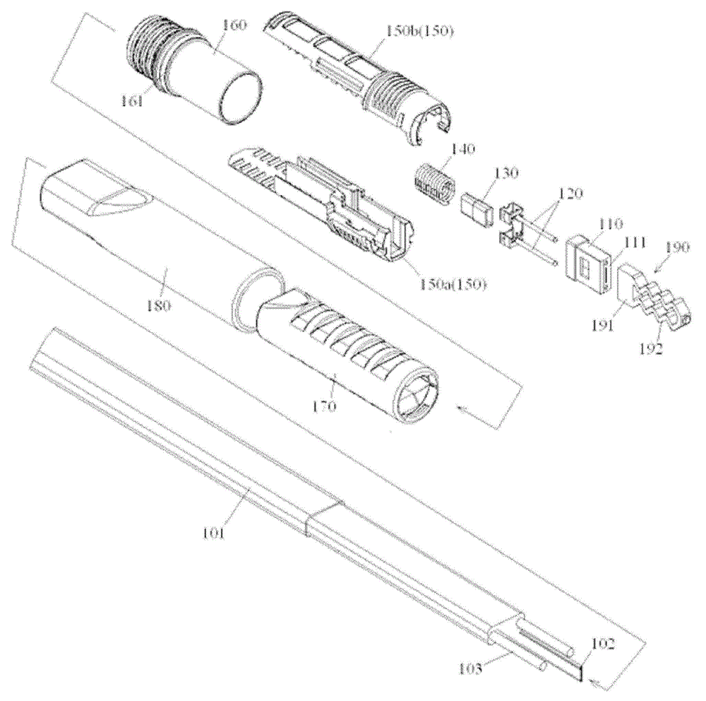
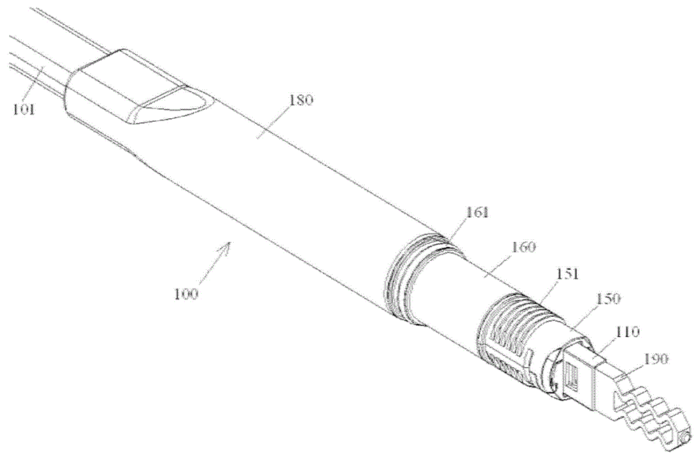
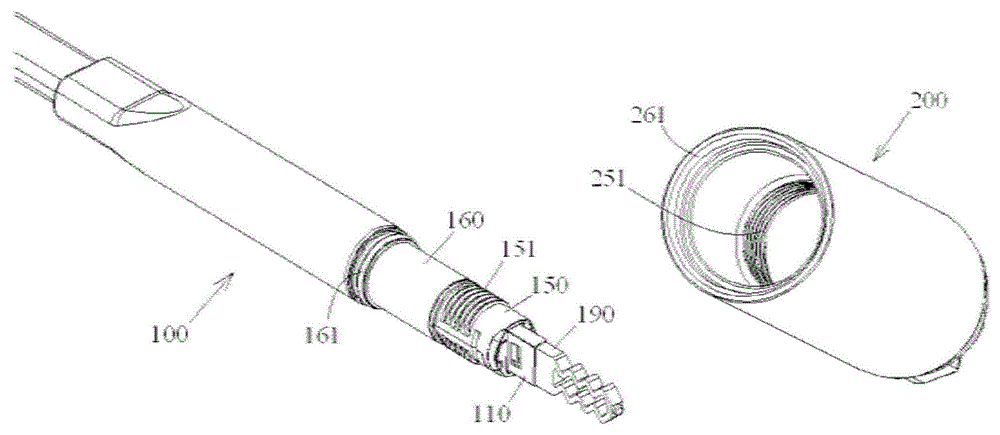
[0079] The technical solutions of the present invention will be further specifically described below through the embodiments and in conjunction with the accompanying drawings. In the specification, the same or similar reference numerals designate the same or similar components. The following description of the embodiments of the present invention with reference to the accompanying drawings is intended to explain the general inventive concept of the present invention, but should not be construed as a limitation of the present invention.

[0080] In addition, in the following detailed description, for purposes of explanation, numerous specific details are set forth in order to provide a comprehensive understanding of the embodiments of the present disclosure. It may be evident, however, that one or more embodiments may be practiced without these specific details. In other instances, well-known structures and devices are shown in diagrammatic form to simplify the drawings.

[0...


PUM


Abstract

The invention discloses a protective cap of an optical fiber inserting core. The protective cap comprises a main body part and an elastic tail part. The main body part is provided with a first side and a second side which are opposite in a first direction. The first side of the main body part is installed at the front end of the inserting core. The elastic tail part is connected at the second side of the main body part and extends for a preset length along the first direction. When the inserting core provided with the protective cap passes through a long and thin pipeline or is installed in the external shell of a connector, the front end surface of the inserting core and the front end surface of the optical fiber can be effectively protected from being externally damaged.

Description

technical field [0001] The invention relates to a ferrule protective cap, a ferrule assembly, an optical fiber connector with the ferrule assembly, a pulling assembly with the ferrule assembly, and an assembly method for the optical fiber connector. Background technique [0002] In the prior art, the design of the enhanced multi-core optical fiber connector based on the porous ferrule is completed by processing and assembling all components in a controlled factory environment. When this design encounters an application environment with limited space (For example: components need to be passed through pipes with limited space), due to the relatively large head of the complete connector, it becomes very difficult to apply in an environment with limited space, and it is even impossible to achieve effective laying of optical cable components. [0003] In the prior art, the design and manufacturing process of the enhanced multi-core optical fiber connector generally adopts the fol...

Claims


Application Information

Patent Timeline
Patent Type & Authority Applications(China)
IPC IPC(8): G02B6/38
Inventor 童朝阳程兴均刘蕾齐龙舟
Owner TYCO ELECTRONICS (SHANGHAI) CO LTD
Why Eureka
Try Eureka