
Cooled Vibration Signal Sensing Device

A vibration signal and sensing device technology, applied in measurement devices, electrical devices, instruments, etc., can solve problems such as limiting the application of accelerometers, and achieve the effect of improving reliability

Active Publication Date: 2018-01-26
AECC COMML AIRCRAFT ENGINE CO LTD
View PDF7 Cites 0 Cited by
  • Summary
  • Abstract
  • Description
  • Claims
  • Application Information

AI Technical Summary

Problems solved by technology

However, the operating temperature of this type of preamplifier components is currently limited to below 350°F, and the temperature in many parts of the engine is higher than this value
Therefore, the complex temperature environment of the engine limits the application of accelerometers with preamplifiers

Method used


Image

  • Cooled Vibration Signal Sensing Device
  • Cooled Vibration Signal Sensing Device
  • Cooled Vibration Signal Sensing Device

Examples


Embodiment Construction

[0025] The technical solutions of the present invention will be described in further detail below with reference to the accompanying drawings and embodiments.

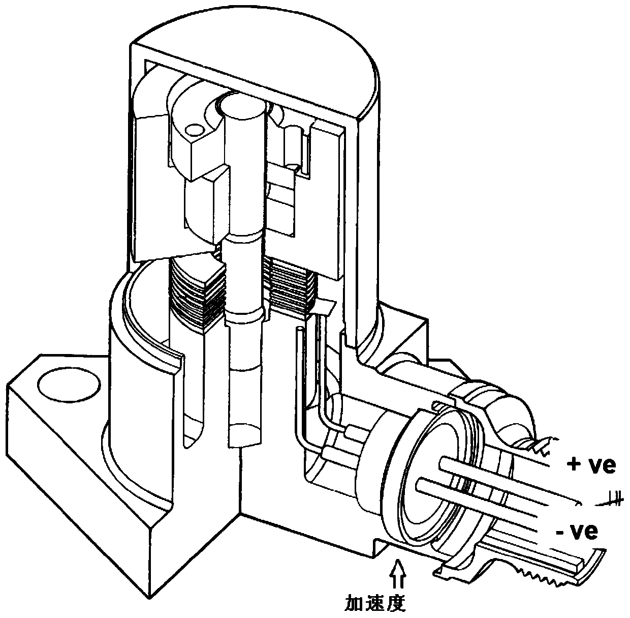
[0026] The present invention aims at the problems existing in the source signal transmission of the existing vibration sensor, and designs a cooling type vibration signal sensing device. The core idea is to introduce cooling air into the accelerometer chamber, and the Cooling keeps it within the operating temperature range, thereby extending the ability of this cooled vibration signal sensing device with preamplifier to adapt to complex temperature environments at multiple locations within the engine.

[0027] Such as Figure 4 Shown is a schematic structural view of an embodiment of the cooling type vibration signal sensing device of the present invention. In this embodiment, the cooled vibration signal sensing device includes: a piezoelectric accelerometer 1, a preamplifier 2, a rectifier ring 3, a cable 4 and an ai...


PUM


Abstract

The invention relates to a cooling type vibration signal sensing device, comprising: a piezoelectric accelerometer, a preamplifier and a cable, the preamplifier is arranged in the accelerometer chamber of the piezoelectric accelerometer, and the preamplifier The preamplifier is electrically connected to the piezoelectric accelerometer and the cable respectively, which also includes: an air duct and a rectification ring, the preamplifier and the cable are separately arranged on both sides of the rectification ring, and pass through the The rectifier ring is electrically connected, the air duct is sleeved on the cable, and a cooling air flow channel is formed between the air duct and the cable, and the accelerometer chamber is provided for exhausting through the air duct Vent for cooling air into the accelerometer chamber. The invention can expand the working range of the piezoelectric vibration sensor with the preamplifier.

Description

technical field [0001] The invention relates to aero-engine state monitoring technology, in particular to a cooling type vibration signal sensing device. Background technique [0002] Engine Vibration Management system (EVM for short), as a part of the engine condition monitoring system, includes all hardware systems and software systems for monitoring and analyzing engine vibration. Most of the currently used EVM systems mainly use one or more vibration sensors installed in certain parts of the engine to detect the vibration caused by rotor imbalance. After the detection signal is received and processed by electronic processing devices with different degrees of complexity, it Crew display or relay to other onboard surveillance equipment. The accuracy and fidelity of an EVM system is largely dependent on the quality of the signal source, which in turn depends primarily on the characteristics of the sensor. The most commonly used vibration sensor at present is a piezoelectr...

Claims


Application Information

Patent Timeline
Patent Type & Authority Patents(China)
IPC IPC(8): G01M15/12G01H11/08
Inventor 蔡宁泊佘云峰侯乃先
Owner AECC COMML AIRCRAFT ENGINE CO LTD
Learn More