
WYSIWYG method and system for dynamically generating user interface

A user interface, dynamic generation technology, applied in the direction of program control devices, etc., can solve the problems of inability to help, long cycle, high labor and material cost, etc.

Inactive Publication Date: 2015-11-25
李志丹
View PDF3 Cites 23 Cited by
  • Summary
  • Abstract
  • Description
  • Claims
  • Application Information

AI Technical Summary

Problems solved by technology

The cost of manpower and material resources is huge and the cycle is long
Moreover, in the above steps, except for reinstalling and deploying the application, the end user cannot help with other tasks and can only wait passively.

Method used


Image

  • WYSIWYG method and system for dynamically generating user interface
  • WYSIWYG method and system for dynamically generating user interface

Examples


Embodiment Construction

[0031] The technical solutions of the present invention will be further described in detail below in conjunction with the accompanying drawings and specific embodiments.

[0032] The present invention can be used in numerous general purpose or special purpose computing system environments or configurations such as: personal computers, server computers, handheld or portable devices, tablet type devices, multiprocessor systems, microprocessor based systems, set top boxes, programmable consumer electronics devices, network PCs, minicomputers, mainframe computers, distributed computing environments including any of the above systems or devices, etc.

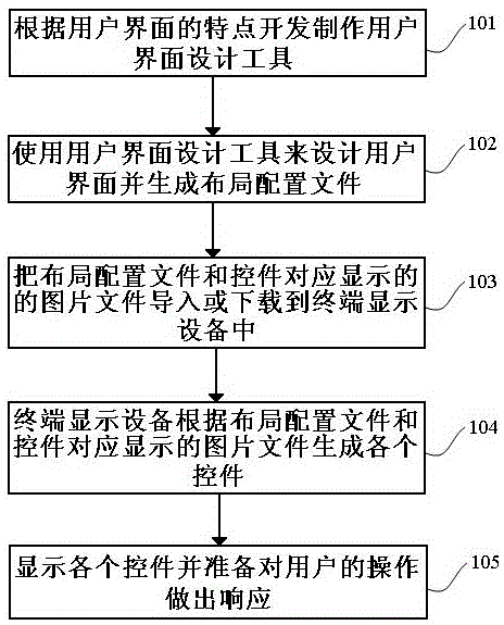
[0033] The flow chart of the method example of the WYSIWYG dynamic generation user interface of the present invention, as figure 1 shown, including:

[0034] In step 101, a user interface design tool must be developed and manufactured according to the characteristics of the system user interface.

[0035] It is necessary to prepare...


PUM


Abstract

The invention discloses a WYSIWYG method for dynamically generating a user interface. The method includes the steps that a WYSIWYG user interface design tool is used for adding and freely dragging various controls to proper display region positions, layout parameters of the controls are set, numbers of the controls are set, and a layout configuration file is generated; the layout configuration file and picture files displayed corresponding to the controls are guided or downloaded into a terminal display device; the terminal display device analyzes the layout configuration file, and the controls are dynamically generated and displayed to a screen of the terminal display device according to the layout parameters and the numbers of the controls and the picture files displayed corresponding to the controls. The invention further discloses a WYSIWYG system for dynamically generating the user interface. In this way, the user interface can be flexibly modified in time according to the change of the situation without changing an application program in the terminal display device, and therefore manpower, material resources and time for modifying the application program are saved.

Description

technical field [0001] The present invention relates to the technical field of computer program application with man-machine interaction interface, in particular to a method and system for dynamically generating layout interface control elements on a two-dimensional display plane. Background technique [0002] In a computer application program with a user interface, if the internal and external conditions change, the current user interface cannot meet the new application requirements, or a new user interface needs to be added, for example: in smart home products, the new A category of smart terminal products has been added, which was not in the previous system, and the operation mode of the new category of smart terminal products is quite different from that of existing products, which requires a new user interface. In this case, it is generally necessary to modify the source code of the application, modify the interface part processing code, and even modify the data process...

Claims


Application Information

Patent Timeline
IPC IPC(8): G06F9/44
Inventor 李志丹
Owner 李志丹
Learn More