
Miniature broadband helical antenna

A helical antenna and broadband technology, which is applied in the field of miniaturized broadband helical antennas, can solve the problems of complex antenna structure and difficult processing, and achieve the effects of flexible array formation, good circular polarization characteristics, and easy processing and realization.

Active Publication Date: 2015-11-25
XIDIAN UNIV +1
View PDF13 Cites 8 Cited by
  • Summary
  • Abstract
  • Description
  • Claims
  • Application Information

AI Technical Summary

Problems solved by technology

However, the structure of the antenna is complex and difficult to manufacture

Method used


Image

  • Miniature broadband helical antenna
  • Miniature broadband helical antenna
  • Miniature broadband helical antenna

Examples


Embodiment 1

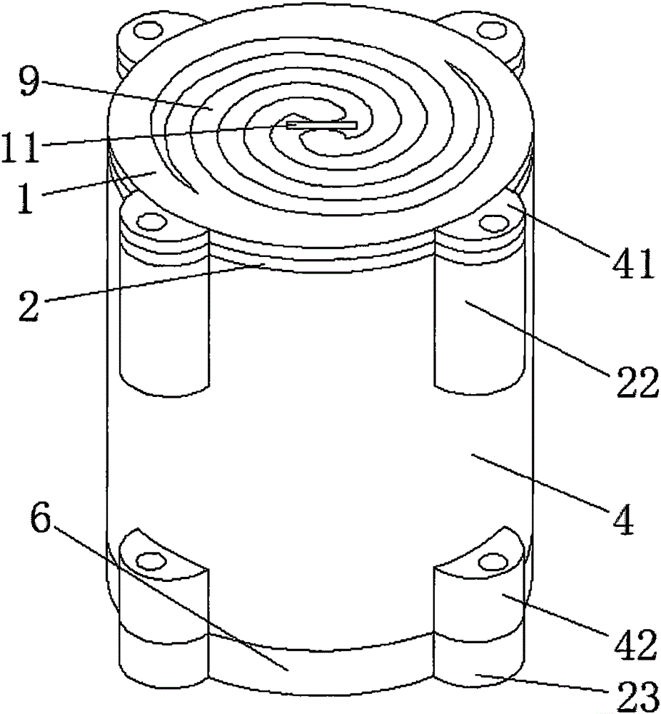
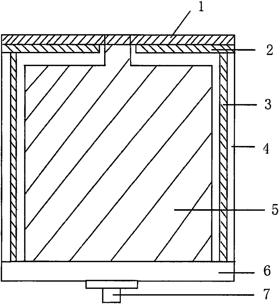
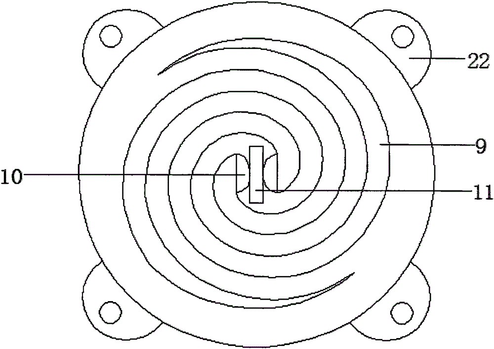
[0027] see Figure 1-9 , a miniaturized broadband helical antenna, which includes a metal cavity 4 with a hollow tubular structure as a whole, a first wave-absorbing material layer 3 is arranged on the inner wall of the metal cavity 4, and a feeding balun 5 is arranged inside it. An antenna layer 1 is fixed on the upper end surface of the metal cavity 4, and a metal back cover 6 is fixed on the lower end surface thereof. The bottom of the antenna layer 1 is provided with a second wave-absorbing material layer 2, and the feeding balun 5 The feeding slot 11 extending upwards from the top is in contact with the planar helical antenna 9, the bottom is provided with a feeding connector 7, and the other end of the feeding connector 7 extends out of a metal back cover 6, and the antenna layer 1 is entirely made of dielectric The material is processed and manufactured, and a planar helical antenna 9 is arranged inside it, and the described feeding slot 11 is located in the middle of t...

Embodiment 2

[0032] see Figure 1-6 , in this embodiment, the wall thickness of the metal cavity 4 described in Embodiment 1 is 1 mm, the diameter is 25 mm, the radius of the first connecting boss 41 and the second connecting boss 42 is 2.5 mm, and the antenna The whole layer 1 is made of dielectric material. The dielectric material adopts a dielectric material with a relative permittivity of 2.2 and a thickness of 0.787. The thickness of the second absorbing material layer 2 is 0.6mm; the feeding balun 5 adopts a relative permittivity 2.2 It is made of dielectric material with a thickness of 0.787. The feed balun 5 adopts an exponential gradient line microstrip structure. The feed balun 5 is connected to the feed connector 7 with a characteristic impedance of 50 ohms to realize the transition from unbalanced feed to balanced In the transition of feeding, at the balanced end, the widths of the exponentially changing structure 17 and the exponentially changing microstrip structure 18 are bo...


PUM


Abstract

The invention discloses a miniature broadband helical antenna. The miniature broadband helical antenna comprises a metal cavity (4), wherein the metal cavity (4) is comprehensively of a hollow tubular structure, a first wave absorption material layer (3) is arranged on the inner wall of the metal cavity (4), a feeding Balun (5) is arranged in the metal cavity (4), an antenna layer (1) is fixedly arranged on the upper end surface of the metal cavity (4), a metal rear cover (6) is fixedly arranged on the lower end surface of the metal cavity (4), a second wave absorption material layer (2) is arranged at the bottom of the antenna layer (1), the top of the feeding Balun (5) is provided with a feeding gap (11) in an upward extension way, the feeding gap (11) is in contact with a planar helical antenna (9), and a feeding connector (7) is arranged at the bottom of the feeding Balun (5). In the miniature broadband helical antenna, the planar helical antenna and the layered wave absorption material are used for forming a radiator, the layered wave absorption material is pasted on the inner wall of the metal cavity, and meanwhile, the design of broadband, circular polarization and miniaturization is achieved; and the reflection between the feeding Balun and the radiator is effectively reduced, and the standing wave characteristic of the antenna is improved.

Description

technical field [0001] The invention relates to the technical field of microwaves and antennas, in particular to a miniaturized broadband helical antenna. Background technique [0002] With the continuous development of ultra-wideband communication technology, communication reconnaissance and electronic warfare technology, miniaturized broadband circularly polarized helical antennas have attracted more and more attention. In these application systems, it is generally required that the antenna has a bandwidth of several octaves, good circular polarization characteristics and miniaturization characteristics at the same time. [0003] As a frequency-invariant antenna, the helical antenna is widely used in the design of this type of antenna. The planar equiangular helical antenna and the Archimedes helical antenna are two basic planar helical antennas. In many design requirements, it is generally hoped that the helical antenna can meet the characteristics of broadband, circular...

Claims


Application Information

Patent Timeline
Patent Type & Authority Applications(China)
IPC IPC(8): H01Q1/38H01Q1/50H01Q17/00
Inventor 黄丘林鲍健慧王新怀魏峰史小卫
Owner XIDIAN UNIV
Learn More