Differential circularly polarized directional antenna

A directional antenna and circular polarization technology, which is applied in the direction of antenna grounding switch structure connection, radiation element structure, etc., can solve the problem of narrow axial ratio bandwidth and achieve good performance, large gain, and good common mode suppression.

Pending Publication Date: 2018-01-19
SOUTH CHINA UNIV OF TECH
View PDF0 Cites 1 Cited by
  • Summary
  • Abstract
  • Description
  • Claims
  • Application Information

AI Technical Summary

Problems solved by technology

However, this existing technology still does not

Method used


Image

  • Differential circularly polarized directional antenna
  • Differential circularly polarized directional antenna
  • Differential circularly polarized directional antenna

Examples


Example Embodiment

[0042] Example 1:

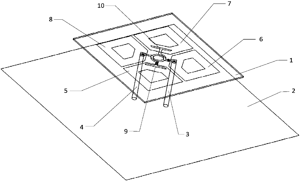
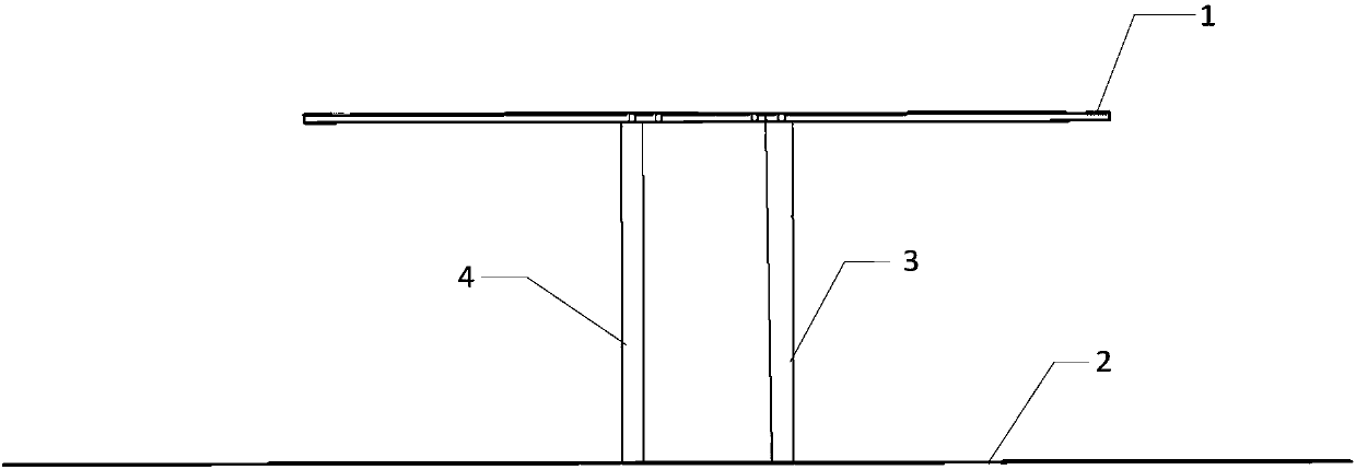
[0043] Such as Figure 1 ~ Figure 3 As shown, this embodiment provides a differential circularly polarized directional antenna. The antenna includes a dielectric substrate 1, a floor 2, a first coaxial line 3, and a second coaxial line 4. The floor 2 is located below the dielectric substrate 1. , The first coaxial line 3 and the second coaxial line 4 are parallel to each other.
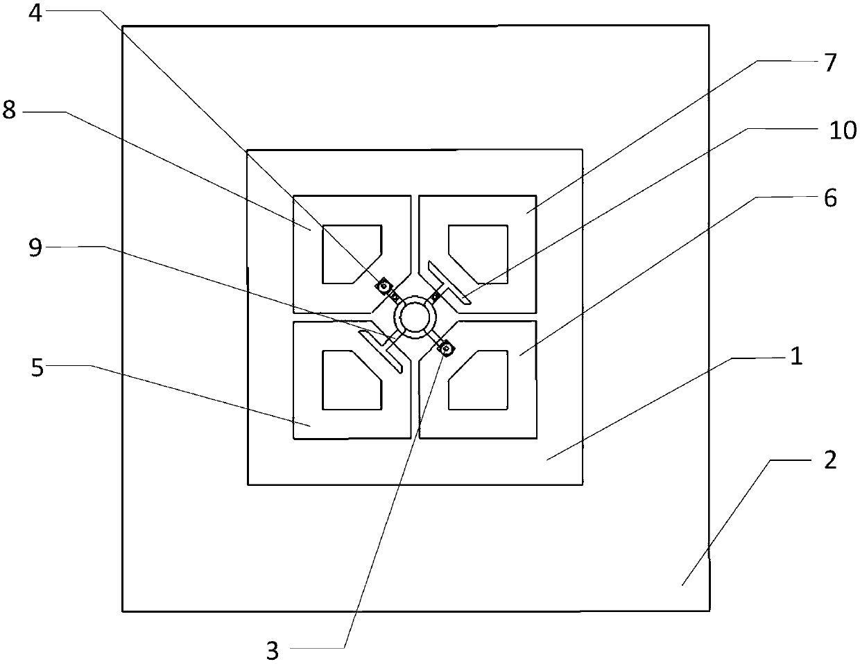
[0044] The area of ​​the upper and lower surfaces of the dielectric substrate 1 is 20%-30% of the area of ​​the floor 2, preferably 25% (ie 1 / 4) of the area of ​​the floor 2, and the center of the dielectric substrate 1 is projected on the floor 2. Coincides with the center of floor 2, from image 3 Can be seen in.

[0045] Such as Figure 4 ~ Figure 6 As shown, the dielectric constant of the dielectric substrate 1 is 4.4, the loss angle is 0.02, its processing technology is mature, the cost is low, the yield is high, the manufacturing process is simple, and it can meet the low cost requ...


PUM


Abstract

The invention discloses a differential circularly polarized directional antenna, which comprises a dielectric substrate, a floor located at the lower part of the dielectric substrate, a first coaxialline and a second coaxial line, wherein the first coaxial line and the second coaxial line are parallel to each other; the dielectric substrate is provided with two 90-degree phase-shift patches and four radiation patches; the four radiation patches are sequentially arranged on the lower surface of the dielectric substrate around the center of the dielectric substrate and are in mirror symmetry; inner conductors at the upper ends of the first coaxial line and the second coaxial line are connected with the two 90-degree phase-shift patches separately and outer conductors are connected with tworadiation patches arranged at opposite angles separately; and the lower ends of the first coaxial line and the second coaxial line pass through the floor. The differential circularly polarized directional antenna is provided with two pairs of dipoles, has a circular polarization characteristic and a difference characteristic, has relatively large impedance bandwidth and axial ratio bandwidth and relatively large gain and can meet the requirements of an LTE mobile phone base station antenna applied to a broadband high-speed wireless communication system of 1.61-2.8GHz.

Description

technical field [0001] The invention relates to a circularly polarized antenna, in particular to a differential circularly polarized directional antenna, which belongs to the technical field of wireless mobile communication. Background technique [0002] In the field of wireless communication, especially mobile communication, multipath effect and polarization mismatch seriously affect communication efficiency and communication quality. How to reduce multipath effect and polarization mismatch has always been a hot research issue. With this kind of solution, the multipath effect and polarization mismatch can be effectively reduced. [0003] The differential antenna can be directly integrated with the differential circuit to reduce the energy loss of the system, which is conducive to the high integration and miniaturization of the system, and the differential antenna has the characteristics of common mode rejection, low cross polarization and high port isolation, so the differe...

Claims


Application Information

Patent Timeline
IPC IPC(8): H01Q1/36H01Q1/38H01Q1/50
CPCY02D30/70
Inventor 涂治红贾凯歌柳炎炎
Owner SOUTH CHINA UNIV OF TECH
Why Eureka
Try Eureka