

Positive current traveling-wave principle component cluster analysis-based closing fault identification method
A technology of forward current and cluster analysis, which is applied in the direction of fault location, electrical components, emergency protection circuit devices, etc., and can solve the problems of insufficient traveling wave identification methods, etc.
- Summary
- Abstract
- Description
- Claims
- Application Information
AI Technical Summary
Problems solved by technology
Method used
Image

Examples
Embodiment 1
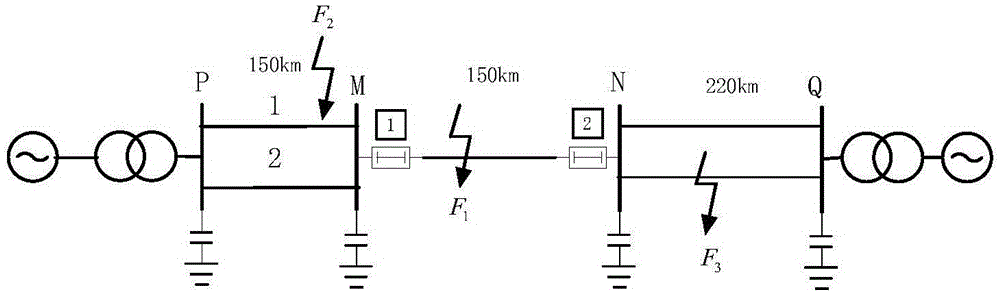
[0026] Embodiment 1: as figure 1 The simulation system model of 500kV transmission line shown, the line to be protected is MN, and the line length is L PM = 150km, L MN = 150km, L NQ =220km, the sampling rate is 1MHz. Assume that the A-phase circuit breaker at the N-terminal of the protected line is in the open state, and the A-phase circuit breaker at the M-terminal end of the protected line performs the closing operation, assuming that there is no fault in the line MN and that a phase-A ground fault occurs 149km away from the M-terminal , the transition resistance is 10Ω, and the initial phase angle is 60°.
[0027] The three-phase current traveling wave and the three-phase voltage traveling wave generated by the closing measurement terminal M of the line are collected. The three-phase voltage and three-phase current traveling waves are transformed into phase-mode using equations (1) and (2), and three line-mode voltage components Δu are extracted α , Δu β and Δu γ a...
Embodiment 2
[0033] Embodiment 2: as figure 1 The simulation system model of 500kV transmission line shown, the line to be protected is MN, and the line length is L PM = 150km, L MN = 150km, L NQ =220km, the sampling rate is 1MHz. Assume that the B-phase circuit breaker at the N-end of the protected line is in the open state, and the B-phase circuit breaker at the M-end of the protected line’s measurement end performs the closing operation, assuming that there is no fault in the line MN and a B-phase ground fault occurs 60km away from the M-end , the transition resistance is 50Ω, and the initial phase angle is 60°.
[0034] The three-phase current traveling wave and the three-phase voltage traveling wave generated by the closing measurement terminal M of the line are collected. The three-phase voltage and three-phase current traveling waves are transformed into phase-mode using equations (1) and (2), and three line-mode voltage components Δu are extracted α , Δu β and Δu γ and the ...
Embodiment 3
[0040] Embodiment 3: as figure 1 The simulation system model of 500kV transmission line shown, the line to be protected is MN, and the line length is L PM = 150km, L MN = 150km, L NQ =220km, the sampling rate is 1MHz. Assume that the A-phase circuit breaker at the N-end of the protected line is in the open state, and the A-phase circuit breaker at the M-end of the measured end of the protected line performs the closing operation, assuming that there is no fault in the line MN and a C-phase ground fault occurs 90km away from the M-end , the transition resistance is 10Ω, and the initial phase angle is 30°.
[0041] The three-phase current traveling wave and the three-phase voltage traveling wave generated by the closing measurement terminal M of the line are collected. The three-phase voltage and three-phase current traveling waves are transformed into phase-mode using equations (1) and (2), and three line-mode voltage components Δu are extracted α , Δu β and Δu γ and th...
PUM
 Abstract
Description
Claims
Application Information