Transmitting device of white light-based LED visible light communication system

A visible light communication and emission device technology, applied in the field of communication, can solve the problems of inconvenient current measurement, large driving current, and high cost of TC integrated chips

Active Publication Date: 2015-11-25
SYSU CMU SHUNDE INT JOINT RES INST +1
View PDF3 Cites 3 Cited by
  • Summary
  • Abstract
  • Description
  • Claims
  • Application Information

AI Technical Summary

Problems solved by technology

This LED driving method has several unavoidable problems: first, the measurement of the current is inconvenient, and it is inconvenient to adjust; A very high magnification is required to drive the triode
Because the output current of general functional boards is very small, only in the milliampere level, it cannot be used directly; thirdly, triode drive is generally only suitable for low-power LED drive, and high-power LED requires a large drive current. current is difficult to reach
[0004] In the PWM control driving LED technology, although the brightness and color temperature of the LED lamp can be well controlled, there are several problems that need to be paid attention to: First, whether the PWM signal is generated by hardware or by software, it requires complex Peripheral circuits, high cost, large device noise
Second, PWM control drive technology is generally only suitable for low-power LED drive
[0005] In the capacitive voltage drop driving technology, the disadvantage of difficult adjustment and difficult measurement of the capacitance is obvious. In addition, the capacitance is a nonlinear element, and the process of charging and discharging takes a certain amount of time, and the problem of delay is unavoidable.
Although IC integrated drive LED technology has effectively improved the shortcomings of the above-mentioned drive technology, the cost of TC integrated chips is too high to be popularized.

Method used


Image

  • Transmitting device of white light-based LED visible light communication system
  • Transmitting device of white light-based LED visible light communication system
  • Transmitting device of white light-based LED visible light communication system

Examples


Embodiment Construction

[0029] In order to make the object, technical solution and advantages of the present invention clearer, the present invention will be described in further detail below in conjunction with specific embodiments and with reference to the accompanying drawings.

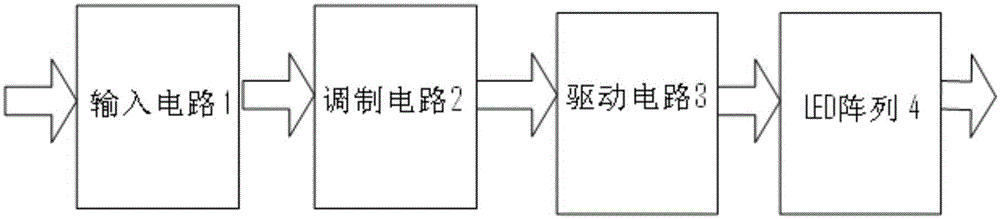
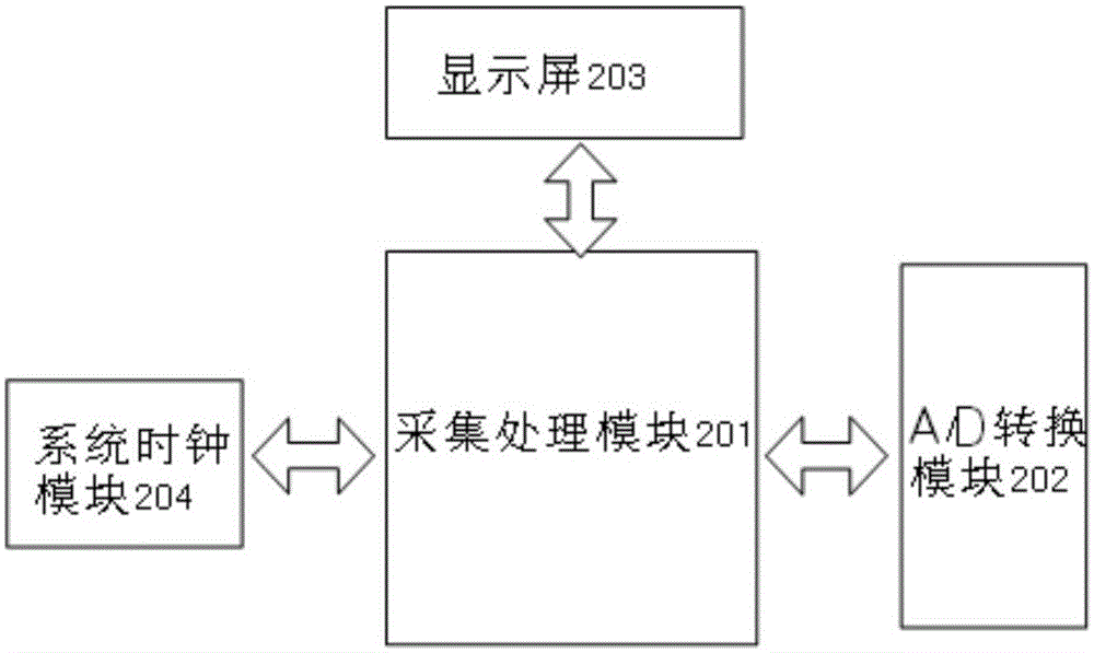
[0030] In one embodiment of the present invention, as figure 2 As shown, it is a schematic structural diagram of a transmitting device of a white LED-based visible light communication system according to an embodiment of the present invention. The transmitting device of the white LED-based visible light communication system includes: an input circuit 1 , a modulating circuit 2 , a driving circuit 3 and an LED array 4 . Wherein, the input circuit 1 can receive the analog electrical signal input from the outside and transmit the analog electrical signal to the modulation circuit 2 , the modulation circuit 2 collects the analog electrical signal, converts it into a digital signal and transmits it to the driving circuit 3 . ...


PUM


Abstract

The invention discloses a transmitting device of a white light-based LED visible light communication system. The transmitting device comprises at least one set of input circuit, modulation circuit, driving circuit and LED array, wherein the input circuit receives analog electric signals inputted from the outside and transmits the analog electric signals to the modulation circuit, the modulation circuit acquires the analog electric signals and converts the analog electric signals into digital signals and transmits the digital signals to the driving circuit, and the driving circuit switches on the LED array according to the digital signals, and the LED array stably emits light according to the modulated signals, and therefore, electro-optic conversion can be realized. With the transmitting device of the invention adopted, the problem of incapability of an LED lamp to work stably when the voltage of modulated signals in a transmitting device is too low or does not accord with required grid pole driving voltage in visible light communication of an LED in the prior art can be completely solved.

Description

technical field [0001] The present invention relates to the communication field, in particular to a transmitting device for a visible light communication system based on a white light LED. Background technique [0002] Currently, if figure 1 As shown, in the white LED-based visible light communication system, the transmitting device can convert the electrical signal into an optical signal, and then send the optical signal to the receiving device through an optical channel, that is, free space, and finally the receiving device can receive the received signal with a certain frequency The optical signal is converted into a raw electrical signal. Among them, the core technology of the emission device of the white LED-based visible light communication system is the electro-optic conversion technology, and the core of the electro-optic conversion technology is the LED driving technology. [0003] Existing LED drive technologies include typical triode (NPN tube) drive, PWM contro...

Claims


Application Information

Patent Timeline
Patent Type & Authority Applications(China)
IPC IPC(8): H04B10/50H04B10/116
Inventor 刘召军莫炜静古今彭灯
Owner SYSU CMU SHUNDE INT JOINT RES INST
Why Eureka
Try Eureka