Air interface synchronizing method, device and system
A technology of air interface synchronization and synchronization source, which is applied in the direction of synchronization devices, electrical components, wireless communication, etc., and can solve the problem that the base station to be synchronized is difficult to detect in time
- Summary
- Abstract
- Description
- Claims
- Application Information
AI Technical Summary
Problems solved by technology
Method used
Image
Examples
Embodiment 1
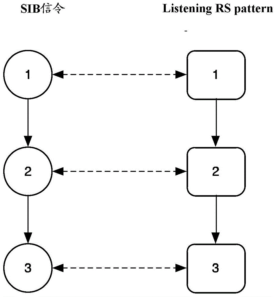
[0120] Such as Figure 5 As shown, it is a schematic diagram of adopting the legacyRS deactivation technology based on the MBSFN subframe in the first case in step 22 . Wherein, listeningRS is a CRS, and the candidate transmission pattern candidateTxPattern1 corresponds to stratumlevel=0, candidateTxPattern2 corresponds to stratumlevel=1, and candidateTxPattern3 corresponds to stratumlevel=2.
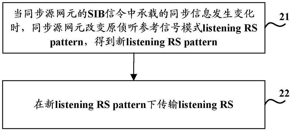
[0121] Before the synchronization information carried in the SIB signaling is changed, the original listeningRSpattern is candidateTxPattern1; after the synchronization information carried in the SIB signaling is changed, the new listeningRSpattern is candidateTxPattern2, and the subframe corresponding to candidateTxPattern1 is configured as an MBSFN subframe.
Embodiment 2
[0123] Such as Figure 6 As shown, it is a schematic diagram of using the MBSFN subframe-based legacyRS deactivation technology in the second case in step 22 . Wherein, listeningRS is a CRS, and the listeningRSpattern candidate set includes: candidate transmission patterns candidateTxPattern1, candidateTxPattern2 and candidateTxPattern3.
[0124]Before the synchronization information carried in SIB signaling is changed, the original listeningRSpattern is candidateTxPattern1, and the subframes corresponding to candidateTxPattern2 and candidateTxPattern3 except candidateTxPattern1 are configured as MBSFN subframes; after the synchronization information carried in SIB signaling is changed, the new listeningRSpattern is candidateTxPattern2, and the subframes corresponding to candidateTxPattern1 and candidateTxPattern3 other than candidateTxPattern2 are all configured as MBSFN subframes.
Embodiment 3
[0126] Such as Figure 7 As shown, it is a schematic diagram of adopting the V-shift-based frequency domain offset technology in the first case and the second case in step 22. Wherein, listeningRS is CRS, and candidateTxPattern1, candidateTxPattern2 and candidateTxPattern3 correspond to different frequency domain offsets respectively.
[0127] Before the synchronization information carried in SIB signaling is changed, the original listeningRSpattern is candidateTxPattern1, corresponding to frequency domain offset 1; after the synchronization information carried in SIB signaling is changed, the new listeningRSpattern is candidateTxPattern2, corresponding to frequency domain offset 2.
[0128] Based on the above introduction of the air interface synchronization method on the side of the network element to be synchronized and the side of the synchronization source network element, the essence of the technical solution of the present invention is further clarified through specific...
PUM
 Abstract
Description
Claims
Application Information
 - R&D
- Intellectual Property
- Life Sciences
- Materials
- Tech Scout
- Unparalleled Data Quality
- Higher Quality Content
- 60% Fewer Hallucinations
Browse by: Latest US Patents, China's latest patents, Technical Efficacy Thesaurus, Application Domain, Technology Topic, Popular Technical Reports.
© 2025 PatSnap. All rights reserved.Legal|Privacy policy|Modern Slavery Act Transparency Statement|Sitemap|About US| Contact US: help@patsnap.com


