Power source apparatus and lighting apparatus

A power supply device and voltage technology, which is applied in the direction of lighting devices, electric light sources, lamp circuit layout, etc., can solve problems such as deterioration of circuit efficiency, and achieve the effect of improving circuit efficiency and reducing offset voltage

Inactive Publication Date: 2015-11-25
TOSHIBA LIGHTING & TECH CORP
View PDF1 Cites 2 Cited by
  • Summary
  • Abstract
  • Description
  • Claims
  • Application Information

AI Technical Summary

Problems solved by technology

[0008] This patent document 1 has the technical problem that if the influence of the offset voltage of the operational amplifier is to be reduced, the circuit efficiency will deteriorate

Method used


Image

  • Power source apparatus and lighting apparatus
  • Power source apparatus and lighting apparatus

Examples


Embodiment approach

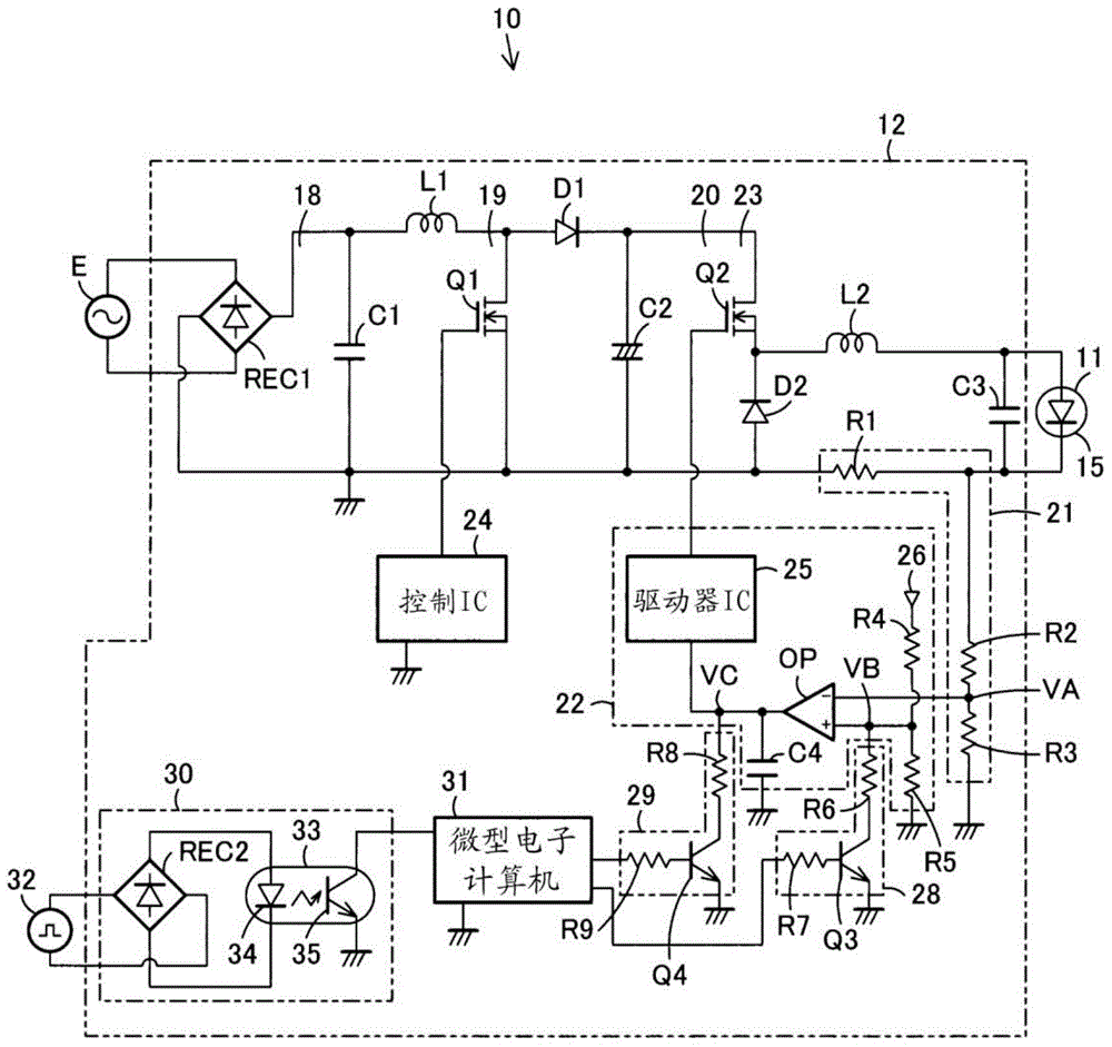
[0020] exist figure 1 Among them, the lighting device 10 includes a light source 11 as a load, and a power supply device 12 that turns on the light source 11 .

[0021] Furthermore, the light source 11 is a light emitting element. Here, LED15 is used as a light emitting element. One or more LED15 may be sufficient. In addition, it is not limited to LED15 as a light emitting element, Other light emitting elements, such as an organic EL, may be sufficient.

[0022] And, the power supply unit 12 has: a rectification filter circuit 18, connected to the commercial AC power supply E; a step-up chopper circuit 19 as a power factor improvement circuit, connected to the output side of the rectification filter circuit 18; a step-down chopper circuit 20, Connected between the output side of the step-up chopper circuit 19 and the LED15; the detection circuit 21 detects a voltage proportional to the current flowing through the LED15; the drive circuit 22 controls the step-down chopper a...


PUM


Abstract

The invention provides a power source apparatus and a lighting apparatus which can reduce impact of offset voltage of an operational amplifier and can increase circuit efficiency. The power source apparatus (12) supplies constant current from a constant circuit (23) to a light source (11). A detection circuit (21) has a detection resistor R1 which is in serial connection with the light source (11) and is used for a voltage which is in proportion to a current which flows through the light source (11). A drive circuit (22) includes an operation amplifier OP and a driver IC (25). The operation amplifier OP inputs a detection voltage and a reference voltage which come from the detection circuit (21). The driver IC (25) controls the constant circuit (23) based on an output voltage of the operation amplifier OP. An output voltage variable mechanism (29) changes an average output voltage which is output from the operation amplifier OP and is input to the driver IC (25). A control portion (31) controls the output voltage variable mechanism (29) based on dimming level.

Description

technical field [0001] Embodiments of the present invention relate to a power supply device and a lighting device that perform constant current control on a load. Background technique [0002] Conventionally, in a power supply device that turns on a light source that is a load, a constant current is supplied from a constant current circuit to the light source to turn on the light source. And, the current flowing through the light source is detected by a detection resistor connected in series with the light source, and the detection voltage (that is, the voltage converted from the current) and the reference voltage are input to the operational amplifier, based on the difference corresponding to the difference between these detection voltage and the reference voltage The output voltage of the operational amplifier is used to feed back the constant current circuit to control the constant current of the light source. And, the reference voltage input to the operational amplifier...

Claims


Application Information

Patent Timeline
Patent Type & Authority Applications(China)
IPC IPC(8): H05B37/02
CPCY02B20/40
Inventor 松本晋一郎石桥久志
Owner TOSHIBA LIGHTING & TECH CORP
Why Eureka
Try Eureka