Boost LED drive circuit

A technology of LED driving and driving circuit, applied in the direction of electric lamp circuit layout, electric light source, lighting device, etc., can solve the problems of low efficiency and poor stability, and achieve high application value, high output impedance and convenient layout symmetry. Effect

Inactive Publication Date: 2016-03-16
WUHU RUIXIN ELECTRONICS TECH CO LTD
View PDF2 Cites 1 Cited by
  • Summary
  • Abstract
  • Description
  • Claims
  • Application Information

AI Technical Summary

Problems solved by technology

At present, the LED constant current backlight drive circuit has the problems of poor stability and low efficiency.

Method used


Image

  • Boost LED drive circuit
  • Boost LED drive circuit

Examples


Embodiment

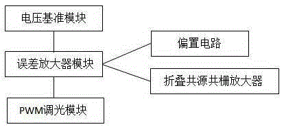
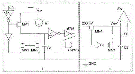
[0015] A boost-type LED drive circuit, the drive circuit includes a voltage reference module, an error amplifier module and a PWM dimming module, the voltage reference module can generate a voltage that has nothing to do with power supply fluctuations and has little relationship with temperature coefficient, so The error amplifier module is connected with the voltage reference module, the error amplifier module includes a bias circuit and a folded cascode amplifier, the bias circuit provides a suitable static operating current for each tube of the main part of the operational amplifier, and the folded common source The common-gate amplifier "shields" the input device so that it will not be affected by the voltage change of the output node. The PWM dimming module is connected to the error amplifier module. LED.

[0016] A starting tube M is added to the voltage reference module 2 , start tube M 2 The gate bias of the grid is derived from the current reference source, the rati...


PUM


Abstract

The invention discloses a boost LED drive circuit. A starting tube M2 is added to a voltage reference module; a gate bias of the starting tube M2 is from a current reference source; when a system normally works, the current reference source works in priority, and then the starting tube M2 is conducted, so that an operational amplifier clamping branch is injected with a current in advance when a voltage reference circuit reaches a normal working point; and normal working voltages are quickly built at two ends of an operational amplifier; the system compensation is I-type compensation; the compensating capacitance is 200pF; and the operational amplifier needs relatively high loading capacity. Due to the constituents of a bipolar operational transconductance amplifier, the boost LED drive circuit has the characteristics of high output impedance, wide transmission band bandwidth and good high-frequency characteristics; symmetrical layout of the domain is facilitated; and the effects of an offset voltage are reduced. A capacitor C2 is added to a PWM dimming module, so that the condition that the current on the capacitor is not released completely when the next charging sequence of the capacitor comes is ensured; the starting process is omitted; and the boost LED drive circuit has high application value.

Description

technical field [0001] The invention relates to the field of LED circuits, in particular to a boost-type LED drive circuit. Background technique [0002] The LED is composed of a PN junction. When the forward bias voltage is greater than the turn-on voltage, spontaneous emission fluorescence is generated. The stronger the radiation energy, the shorter the emitted wavelength, and vice versa, the longer the wavelength. As a backlight widely used at present, the advantages of LED are quite obvious. The main advantages are: (1) Green and environmental protection: it uses semiconductor technology to emit light, and does not contain harmful substances such as mercury, which meets the current environmental protection needs of the world; (2) Low power Power consumption, luminous efficiency above 100lm / W, power consumption can be reduced by more than 30%. The use of dynamic local dimming technology can further reduce power consumption; (3) Long life: the working life is as long as 1...

Claims


Application Information

Patent Timeline
Patent Type & Authority Applications(China)
IPC IPC(8): H05B37/02
Inventor 朱成华崔俊国
Owner WUHU RUIXIN ELECTRONICS TECH CO LTD
Why Eureka
Try Eureka