Particle beam projection chamber and particle beam treatment device

A particle beam and irradiation device technology, applied in the field of irradiation room, can solve problems such as detrimental efficient use of particle beam therapy devices, and achieve the effects of improving utilization efficiency and shortening operation time

Inactive Publication Date: 2015-11-25
HITACHI LTD
View PDF6 Cites 3 Cited by
  • Summary
  • Abstract
  • Description
  • Claims
  • Application Information

AI Technical Summary

Problems solved by technology

Compared with the time required for irradiation of about 5 minutes, the setting operation before irradiation takes twice as long, and as a result, the efficient use of particle beam therapy equipment is impaired

Method used


Image

  • Particle beam projection chamber and particle beam treatment device
  • Particle beam projection chamber and particle beam treatment device
  • Particle beam projection chamber and particle beam treatment device

Examples


Embodiment approach 1

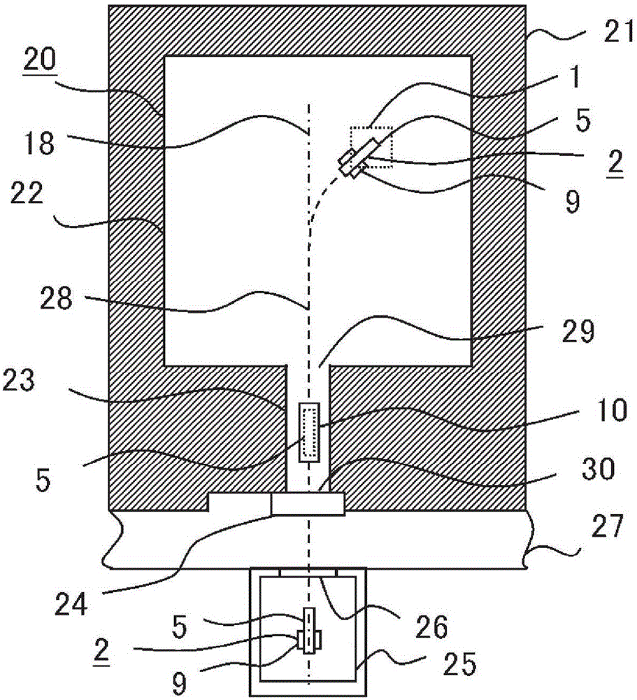
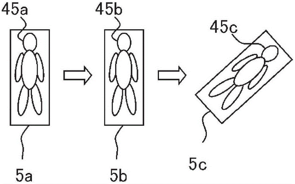
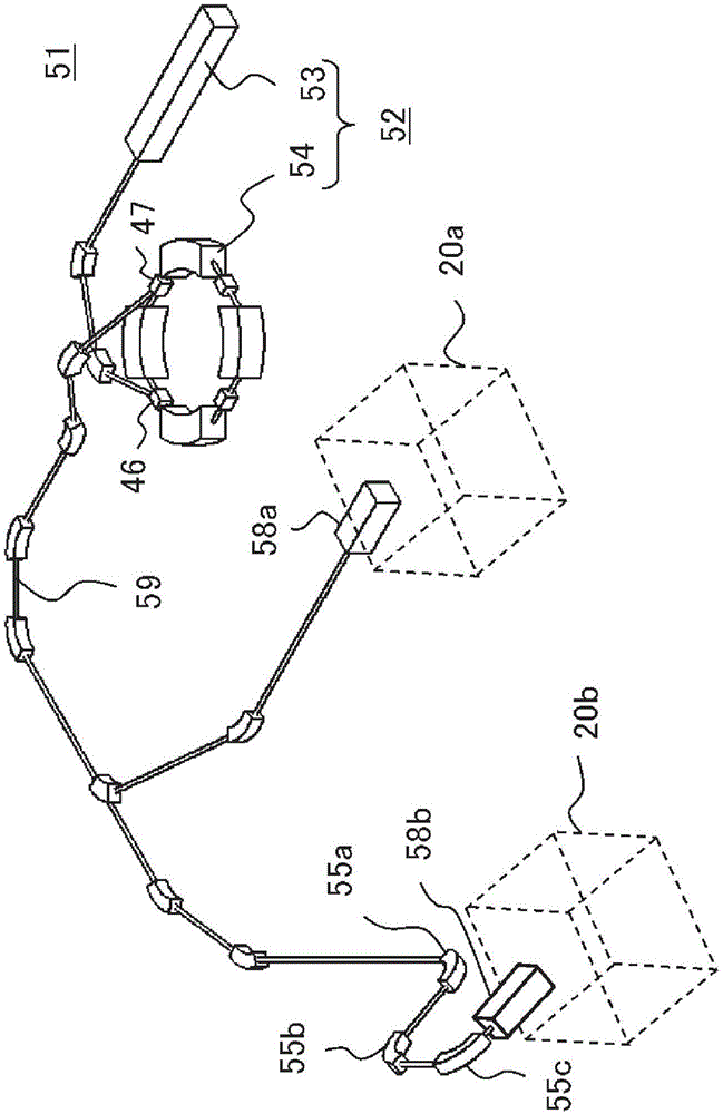
[0028] The particle beam irradiation room and the particle beam therapy apparatus including the particle beam irradiation room of the present invention will be described. figure 1 is a diagram showing a particle beam irradiation chamber according to Embodiment 1 of the present invention, figure 2 It is a figure explaining the posture of a patient when transporting a patient in Embodiment 1 of this invention. image 3 It is a schematic configuration diagram of a particle beam therapy apparatus including a particle beam irradiation room of the present invention, Figure 4 yes means image 3 A diagram of the structure of the particle beam irradiation device. Figure 5 It is a figure which shows the patient position setting apparatus of this invention. Figure 6 yes means Figure 5 diagram of the patient table, Figure 7 yes means Figure 5 A diagram of the delivery device. The particle beam irradiation room 20 according to Embodiment 1 of the present invention (referred t...

Embodiment approach 2

[0052] Figure 9 It is a figure which shows the particle beam irradiation chamber of Embodiment 2 of this invention. The difference between the particle beam irradiation chamber 20 of Embodiment 2 and the particle beam irradiation chamber 20 of Embodiment 1 is that a shield door 24 is also provided at the entrance 29 of the irradiation execution chamber. Figure 9 24b is attached to the shield door when the patient 45 placed on the top plate 5 is transported, and 24c is attached to the shield door when the particle beam is irradiated. In Embodiment 2, since a plurality of shielding doors 24 are provided, the shielding effect of each of the plurality of shielding doors can be reduced compared to shielding leakage radiation generated during particle beam therapy with only one shielding door. Therefore, design restrictions can be reduced compared to the shield door 24 of the first embodiment, and the shield door 24 can be prepared more easily than the shield door 24 of the first...


PUM


Abstract

An objective of this particle beam projection chamber is to ensure that after a patient is positioned on somewhere other than the patient bed in a projection region used when actually projecting a particle beam, the amount of positional deviation in the positioning state of the patient is within an allowable range when being moved to the projection region from the entrance of the projection chamber. This particle beam projection chamber (20) comprises: a projection execution chamber (22) wherein a wherein a patient bed (2) comprising a detachable top board (5) and a drive device (9) for driving the top board (5) is placed, said projection execution chamber (22) being surrounded by a shield wall (21); a path (23) which is disposed on a side in the shield wall (21) where an antechamber (25) in which a patient (45) is to be positioned on the top board (5) is located, such that the patient (45) positioned on the top board (5) may pass into the projection execution chamber (22) by a conveyance device (10) in a straight line; and a shield door (24) which shields radiation leaking at or less than a managed value when the particle beam is projected, said shield door (24) being provided at a projection chamber entrance (30) which is located on the antechamber (25) side of the path (23).

Description

technical field [0001] The present invention relates to an irradiation chamber of a particle beam therapy apparatus used for treating cancer and the like. Background technique [0002] In recent years, among particle beam therapy devices for treating cancer, cancer therapy devices using protons and heavy ions (particularly referred to as particle beam therapy devices) have been developed and constructed. It is well known that particle beam therapy using protons, heavy ions, etc., can irradiate cancer patients intensively and treat normal cells without affecting normal cells, compared with conventional radiation therapy such as X-rays and gamma rays. [0003] In particle beam therapy, it is important to irradiate tumors such as cancer with high precision. Therefore, in order that the patient does not deviate from the position of the bed (patient table) in the treatment room (irradiation room) during the particle beam therapy, it is fixed to the ceiling of the bed using fixtu...

Claims


Application Information

Patent Timeline
Patent Type & Authority Applications(China)
IPC IPC(8): A61N5/10
CPCA61N5/1077A61N2005/1087A61N2005/1094A61N2005/1063E04B1/92E04B2001/925E06B5/18G21F7/005
Inventor 田尻真也高桥理
Owner HITACHI LTD
Why Eureka
Try Eureka