

Reduction of false positive on reagent test devices
A technique for reagents, testing and analysis, applied in the field of analyzers
Inactive Publication Date: 2015-11-25
SIEMENS HEALTHCARE DIAGNOSTICS INC
View PDF13 Cites 5 Cited by
- Summary
- Abstract
- Description
- Claims
- Application Information
AI Technical Summary
Problems solved by technology
[0012] However, in some cases, the detectable response of the reagent pad and sample results in one or more false positive results indicating the detection of a component in the sample, such as an analyte
Method used
View moreImage
Smart ImageViewing Examples

Examples
Embodiment Construction
[0018] The following detailed description refers to the accompanying drawings. The same reference numbers in different drawings may identify the same or similar elements.
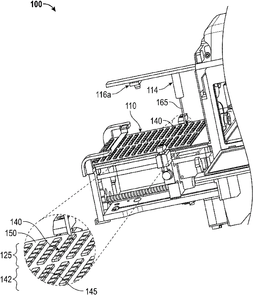
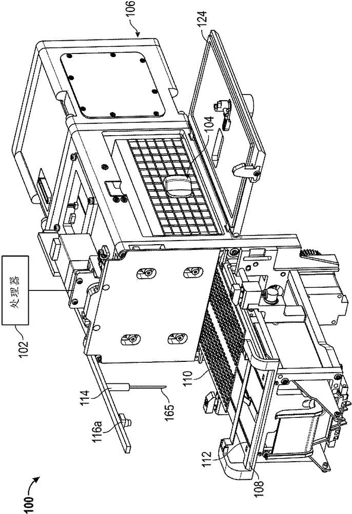
[0019] The mechanism proposed in this disclosure circumvents the problems described above. In one embodiment, the reagent analyzer includes a test analysis mechanism configured to read a first sample of sample bound to a reagent, and a second sample of sample (which may or may not be combined with another reagent) reagent binding) to output one or more first signals indicating that the test assay mechanism reads the first sample bound to the reagent and the test assay structure reads the second sample.
Login to View More PUM
 Abstract
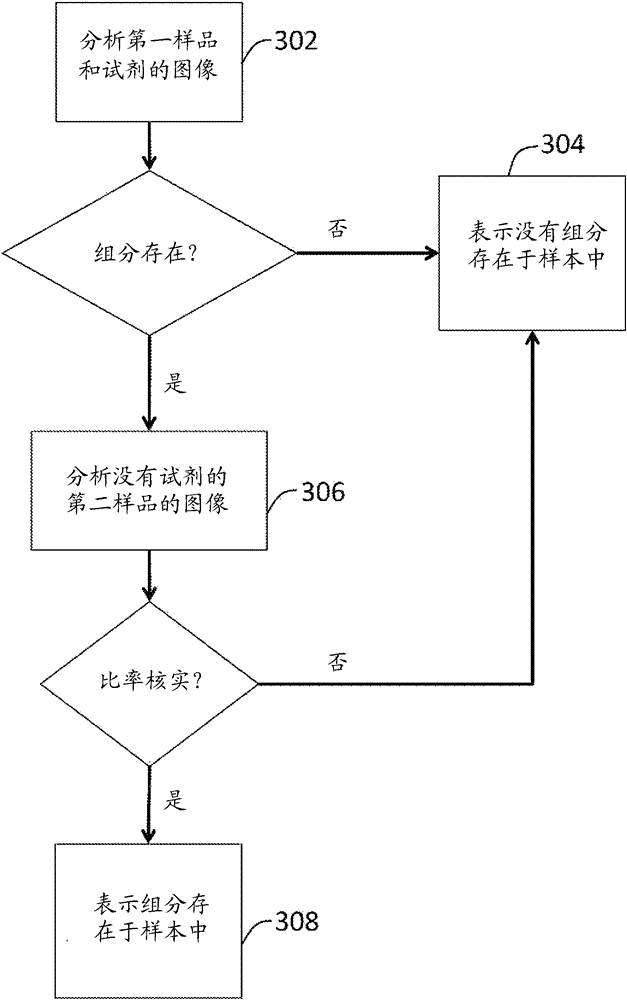
Methods and systems are disclosed including a reagent analyzer, comprising a test analyzing mechanism, such as an optical imaging system, configured to read a first sample of a specimen combined with a reagent configured to react with the sample in a presence of an analyte of interest and a second sample of the specimen that is not combined with a reagent, and to output one or more first signals indicative of the test analyzing mechanism reading the first and second samples; and a processor receiving the one or more first signals and executing logic to analyze the second sample responsive to the processor determining that the analyte of interest is present in the first sample. The processor may execute logic to analyze the second specimen utilizing one or more ratio algorithm and comparing the results of the algorithm against predetermined values indicative of expected color.
Description
[0001] Cross References to Related Applications [0002] This application claims the benefit of US Provisional Application Serial No. 61 / 764,905, filed February 14, 2013, under 35 U.S.C. 119(e), the entirety of which is expressly incorporated herein by reference. technical field [0003] The present disclosure relates generally to analyzers for reagent cards, and more particularly, but not in a limiting manner, to methods and systems for reducing false positive readings in analyzers for multi-profile reagent cards. Background technique [0004] Reagent test strips are widely used in many fields, including medicine and clinical chemistry. Reagent test strips typically have one or more reagent test areas, each capable of undergoing a color change in response to contact with a liquid sample. Liquid samples typically contain one or more components, substances or properties of interest. The presence and concentration of these components of interest in the sample can be determin...
Claims
Login to View More Application Information
Patent Timeline
 Patent Type & AuthorityApplications(China)
IPC IPC(8): C40B60/12G01N21/75G01N33/48
CPCG01N21/78G01N21/253G01N21/274Y10T436/146666G01N33/728
InventorC.T.齐默尔G.W.莱因黑默
OwnerSIEMENS HEALTHCARE DIAGNOSTICS INC