Four-head surfacing machine

A technology of surfacing welding machine and welding torch, which is applied in the field of surfacing welding machines, which can solve the problems of low surfacing welding efficiency, damage, and unstable structure of the whole machine, and achieve the effect of improving efficiency and high-efficiency surfacing welding

Inactive Publication Date: 2015-12-02
ZHANGJIAGANG HONGXING ENVIRONMENTAL PROTECTION EQUIP
View PDF10 Cites 2 Cited by
  • Summary
  • Abstract
  • Description
  • Claims
  • Application Information

AI Technical Summary

Problems solved by technology

[0003] In the existing surfacing welding machine, the surfacing welding is mainly carried out by single-head or double-head welding torches, and the efficiency of surfacing welding is low. At the same time, the structure of the whole machine in the existing equipment is unstable and easy to cause damage. If four Welding with welding torches needs to overcome the problems of the arrangement of welding torches and the mobility of welding torches

Method used


Image

  • Four-head surfacing machine
  • Four-head surfacing machine
  • Four-head surfacing machine

Examples


Embodiment 1

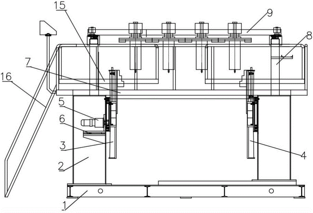
[0018] combine Figure 1-3 , the present invention proposes a four-head surfacing welding machine, including a machine base 1, a fixing seat 2 located on the machine base 1, and a first chuck 3 and a second chuck 4 are arranged oppositely on the fixing base 2 , the first chuck 3 is connected to the output end of the motor 5, the fixed seat 2 is provided with a first chute 6, the motor 5 is installed on the first chute 6, and the motor 5 is placed on the The first chute 6 is far away from or close to the first chuck 3, when the motor 5 moves away from the first chuck 3 on the first chute 6, the output end of the motor 5 is separated from the chuck, and the chuck stops Rotation is easy to disassemble, which solves the problem that the chuck is not easy to disassemble due to its heavy weight.

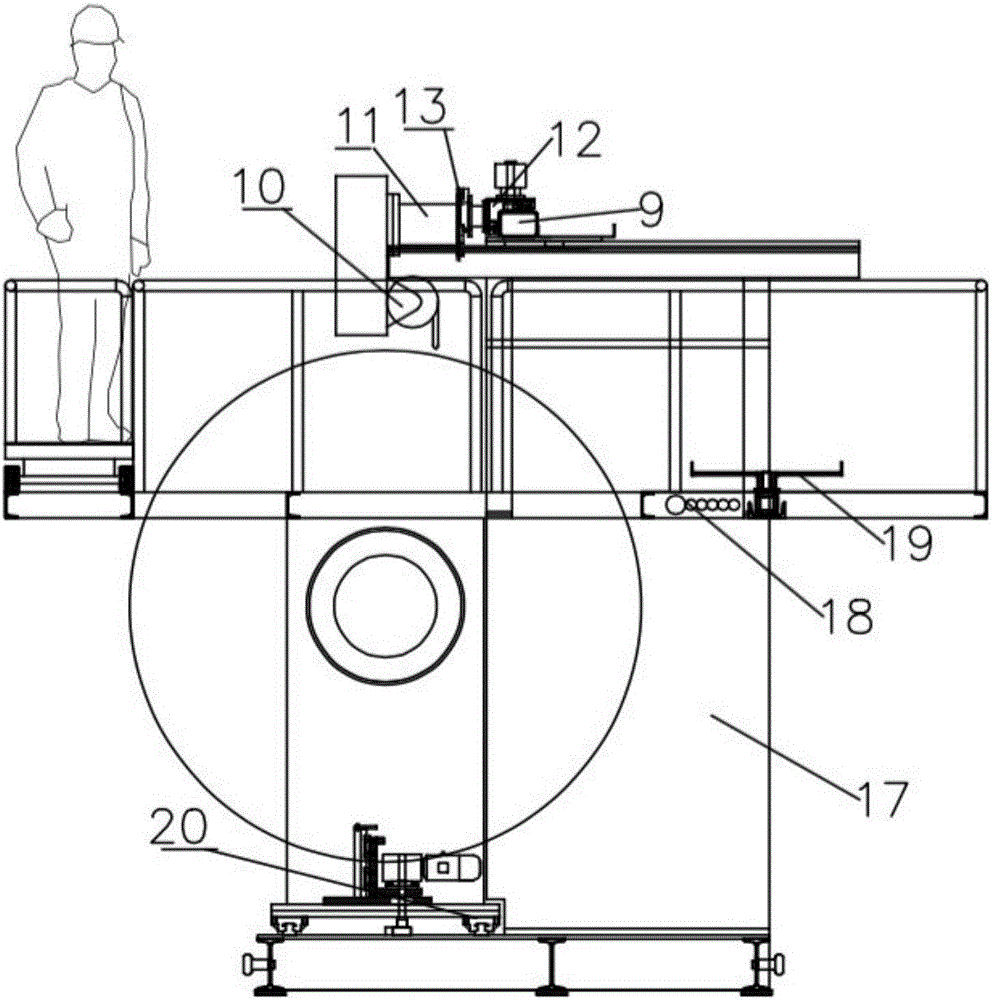
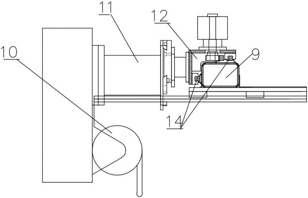
[0019] The fixed seat 2 is provided with a fixed platform 7, the upper part of the fixed platform 7 is provided with a bracket 8, and the bracket 8 is provided with a slide rail 9, and fo...

Embodiment 2

[0021] In this embodiment, on the basis of Embodiment 1, a welding machine room 17 is provided at the lower part of the fixed platform 7, and the welding machine room 17 is used to place a power supply or a spare welding machine. At the same time, the fixed platform 7 on the upper part of the welding machine room 17 Inside is inserted with some steel pipes 18 for routing, and the lines in the welding machine room 17 are connected to the upper welding device by the steel pipes 18, effectively placing the lines around the fixed platform 7, which affects the work.

[0022] In addition, a tray 19 is provided on the side of the fixed platform 7, and the tray 19 is movably connected to the side of the fixed platform 7 through a steel channel. The tray 19 can slide on the side of the fixed platform 7, and the welding wire is placed on the tray 19. .

Embodiment 3

[0024] On the basis of Embodiment 1 or 2, an additional movable platform 15 is provided on the fixed platform 7, and the movable platform 15 includes a stand plate positioned on the fixed platform 7, and handrails are provided on both sides of the stand plate, so One side of the movable platform 15 is provided with a ladder 16, the movable platform 15 is a frame structure, placed on the fixed platform 7, the position can be adjusted according to the needs for the operator to stand, it can be removed when not in use, it is very convenient to use, and it can also be used For carrying heavier objects, the staff stands on the fixed platform 7 to promote the activities and the platform.


PUM


Abstract

The invention discloses a four-head surfacing machine. The four-head surfacing machine comprises a machine base, and a fixed base positioned on the machine base, wherein a first chuck and a second chuck are oppositely arranged on the fixed base; the first chuck is connected with the output end of a motor; a first slide slot is formed in the fixed base; the motor is mounted on the first slide slot; the motor is far from or close to the first chuck on the first slide slot; a fixed platform is arranged on the fixed base; a bracket is arranged on the upper part of the fixed platform; a slide rail is arranged on the bracket; and four surfacing structures are arranged and mounted on the slide rail. With four welding heads, the machine can carry out surfacing more efficiently; the four welding heads move left and right on the slide rail to carry out surfacing, so that the efficiency of the four-head surfacing machine is improved by four times in comparison with that of a conventional surfacing machine; the arrangement problem of four welding guns is solved, and the welding guns are prevented from being damaged because of factors such as a too high temperature and the like; and the positions of the chucks, the motor and the welding guns can be adjusted, so that the four-head surfacing machine is suitable for surfacing of rollers with different specifications.

Description

technical field [0001] The invention relates to the technical field of surfacing welding machines, in particular to a side tightening mechanism of a welding machine. Background technique [0002] During the production process of metallurgical enterprises, a batch of large rollers that cannot meet the production requirements due to surface defects will be replaced regularly. Due to the large length and diameter of these rollers, it is very difficult to repair them. Surface surfacing is a key process for repairing large rolls with surface defects. Due to the lack of suitable surfacing equipment, not only the surfacing efficiency is low, but also the uniformity of the surface surfacing cannot be guaranteed. If these rollers are scrapped, it will cause huge waste. Therefore, how to repair and reuse these large rollers with surface defects has become one of the bottlenecks for reducing the production cost of iron and steel enterprises. [0003] In the existing surfacing welding...

Claims


Application Information

Patent Timeline
IPC IPC(8): B23K37/02B23K37/04B23K37/047B23K37/00
CPCB23K37/0229B23K37/00B23K37/0435B23K37/047
Inventor 范志刚范忠祥朱金海
Owner ZHANGJIAGANG HONGXING ENVIRONMENTAL PROTECTION EQUIP
Why Eureka
Try Eureka