Tool for making wood cabinet having clock and method of making same
A technology for making tools and lockers, which is applied to manufacturing tools, wood processing appliances, circular saws, etc., can solve problems such as low efficiency and laborious work, and achieve high precision and high efficiency.
- Summary
- Abstract
- Description
- Claims
- Application Information
AI Technical Summary
Problems solved by technology
Method used
Image

Examples
Embodiment 2
[0040] Embodiment two, the difference with embodiment one is:
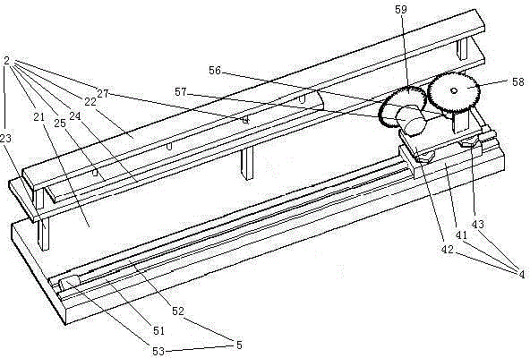
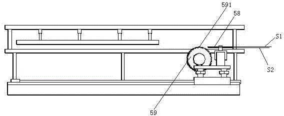
[0041] see Figure 6 , The translation mechanism 5 includes a rack 26, a travel gear 55 and a third motor that drives the travel gear. The rack 26 is disposed on the base 21 . The rack gear 26 extends in the front-rear direction. The traveling gear 55 is disposed on the rotating shaft 1 . The rotating shaft 1 is rotatably connected to the lower seat 41 . Traveling gear 55 meshes with rack 26 together. The lower seat 41 is also provided with a balance roller 54 . The balance roller 54 is connected together with the lower seat 41 by the support rod 44 . The balance roller 54 is supported on the base 21 . Several lubricating mechanisms 8 are arranged in the travel gear 55 . The number of lubricating mechanisms 8 is equal to the number of teeth of the traveling gear 55 .
[0042] see Figure 7 , The lubricating mechanism 8 includes an oil outlet 81 , an air supply port 82 , a sealing head 83 , a first spring...
Embodiment 3
[0050] Embodiment three, the difference with embodiment two is:
[0051] see Figure 11 , The lower end of the base 21 is provided with some anti-skid pads 7 . The anti-skid pad 7 includes an outer suction cup 72 connected with the base 21 , an inner suction cup 73 and a flow channel 71 arranged in the outer suction cup 72 . The suction end 731 of the inner suction cup protrudes from the suction end 721 of the outer suction cup. Both the outer suction cup 72 and the inner suction cup 73 are made of rubber. A suction groove 74 is formed between the outer suction cup 72 and the inner suction cup 73 . Several elastic ribs 75 are arranged in the adsorption groove 74 . The elastic ribs 75 are distributed along the circumferential direction of the inner suction cup 73 . One end of the elastic tendon 75 is connected together with the outer suction cup 72, specifically in an integrated structure. The inner suction cup 73 at the other end of the elastic rib 75 is connected togeth...
Embodiment 4
[0055] Embodiment four, the difference with embodiment three is:
[0056] see Figure 13 , The workpiece supporting platform 24 is provided with a tilting self-disconnecting switch 9 for controlling the stop of the third motor. The tilt self-off switch 9 is provided on the lower surface of the work support table 24 . The tilting self-disconnecting switch 9 includes a housing 91 , a terminal pin 92 , a power-off spring 93 , a conductive sheet 94 , a weight guide cavity 95 , a weight 96 , a swing arm 97 and a barb 98 .
[0057] The shell 91 is made of insulating material, specifically made of plastic. The shell is connected with the workpiece supporting platform 24 together. The housing 91 is provided with an assembly cavity 911 . A recess 915 is formed in the middle of the bottom wall of the assembly cavity 911 .
[0058] There are two connecting pins 92. The two connecting pins 92 are distributed along the left and right directions. The terminal pin 92 is fixed on the b...
PUM
 Abstract
Description
Claims
Application Information