Counterweight control method of tire crane with movable counterweight system

A technology of movable counterweight and control method, which is applied in the field of tire cranes, can solve problems such as potential safety hazards and increased counterweight, and achieve the effects of prolonging service life, ensuring construction safety, and realizing moment balance

Active Publication Date: 2017-03-15
宜昌常丰港机制造有限公司
View PDF6 Cites 0 Cited by
  • Summary
  • Abstract
  • Description
  • Claims
  • Application Information

AI Technical Summary

Problems solved by technology

The problem is that during the lifting construction, the other end of the turntable relative to the boom should be equipped with a counterweight to keep a balance with the lifting weight, and as the lifting capacity increases, the counterweight also needs to be increased accordingly
[0003] There is also a plan to set the movable counterweight, but the manual control of the movable counterweight is usually used, which has certain safety hazards. At present, there is no automatic control of the movable counterweight.

Method used


Image

  • Counterweight control method of tire crane with movable counterweight system
  • Counterweight control method of tire crane with movable counterweight system
  • Counterweight control method of tire crane with movable counterweight system

Examples


Embodiment 1

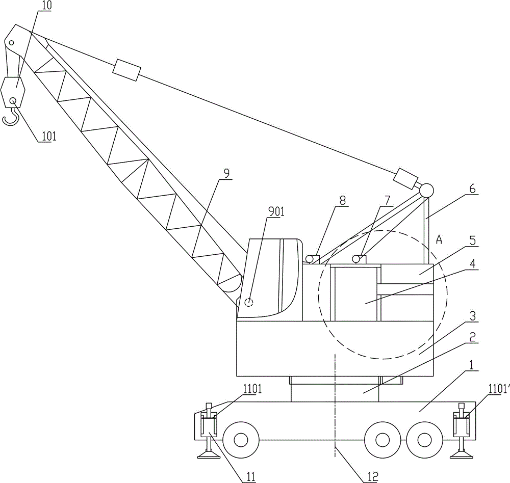
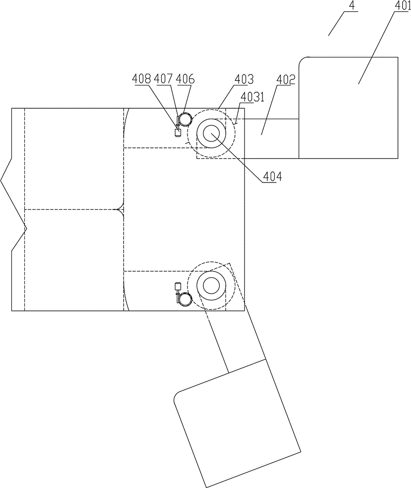
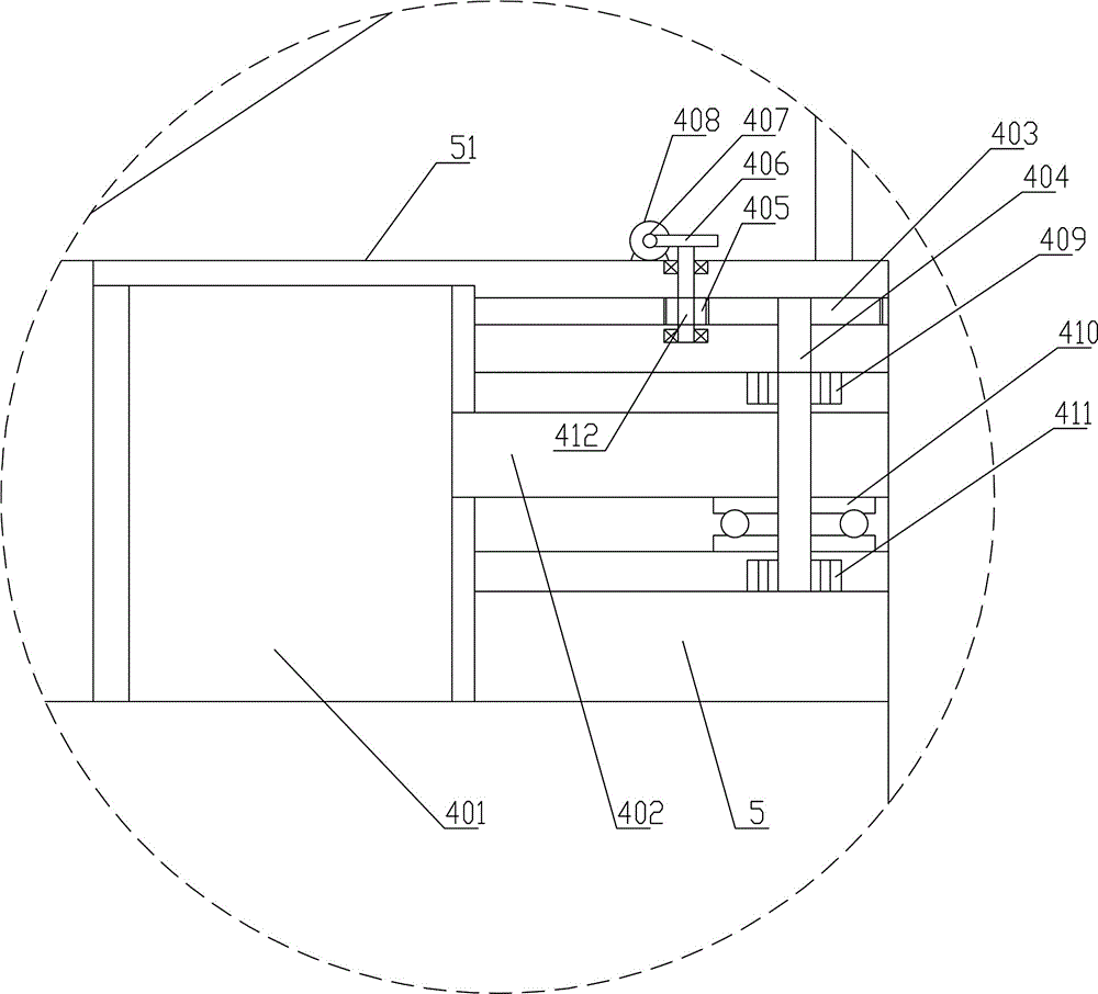
[0037] Such as Figure 1~4 Among them, a tire crane counterweight control method with a movable counterweight system, the turntable 3 is connected with the car body 1 through the column 2, the turntable 3 is provided with a movable counterweight device 4, and the structure of the movable counterweight device 4 is: a movable counterweight The weight 401 is connected with the fixed seat 5 through the connecting rod 402 and the vertical shaft 404, the vertical shaft is located near the tail of the fixed seat 5, and the top of the vertical shaft 404 is provided with a gear plate 403,

[0038] The driving device is connected with the toothed disc 403 , and the driving device drives the vertical shaft 404 and the movable counterweight 401 to rotate through the toothed disc 403 .

[0039] The boom 9 is hinged with the car body 1, and the upper end of the boom 9 is provided with a gravity sensor for detecting the suspension hook 10, and the gravity sensor can also be arranged on the s...

Embodiment 2

[0057] A tire crane counterweight control method with a movable counterweight system, the turntable 3 is connected to the car body 1 through the column 2, the turntable 3 is provided with a movable counterweight device 4, and the structure of the movable counterweight device 4 is: a movable counterweight 401 The connecting rod 402 and the vertical shaft 404 are connected to the fixed seat 5, and the driving device drives the vertical shaft 404 and the movable counterweight 401 to rotate;

[0058] The four corners of the car body 1 are provided with spiral legs 11 , on which are pressure sensors for detecting the pressure received, and a rotation angle sensor is also provided near the column 2 for detecting the rotation angle of the turntable 3 . Include the following steps:

[0059] 1. Detect each pressure sensor and calculate whether the difference between each pressure sensor exceeds the upper limit. If it is, stop the protection, otherwise the next step; the upper limit her...


PUM


Abstract

Provided is a control method for a balance weight of a tire crane with a movable balance weight system. According to the method, a gravity sensor and a tilt angle sensor are detected, a tilt angle and a sling load are converted to moment, a movable balance weight device is started, and the rotation angle of the movable balance weight device is detected for feedback. By means of the steps, balance control over a movable balance weight of the tire crane is achieved. Alternatively, spiral landing legs are arranged at the four corners of a crane body, pressure sensors used for detecting pressure exerted on the spiral landing legs are arranged on the spiral landing legs, the difference values between the pressure sensors are compared, the movable balance weight device is started, and the rotation angle of the movable balance weight device is detected for feedback, and by means of the steps, balance control over the movable balance weight of the tire crane is achieved. According to the control method for the balance weight of the tire crane with the movable balance weight system, by the adoption of the steps, automatic control over the movable balance weight can be achieved, the movable balance weight can be matched with the moment of the sling load, moment balance is achieved, construction safety is ensured, and the service life of equipment is prolonged.

Description

technical field [0001] The invention relates to the field of tire cranes, in particular to a tire crane counterweight control method with a movable counterweight system. Background technique [0002] The tire crane is a boom rotating crane that uses a tire-type chassis to travel. It is composed of a car body part and a turntable part, and a boom and an operating room are set on the turntable. The tire crane has the advantages of good mobility, convenient transfer, efficient construction and safety. The problem that exists is, during hoisting construction, turntable should be provided with counterweight relative to the other end of boom, to keep balance with hoisting weight, and along with the increase of hoisting capacity, counterweight also needs to increase correspondingly. In this way, the dead weight of the tire crane is higher, which affects the driving mobility. How to reduce the dead weight while increasing the hoisting weight has always been a technical problem for...

Claims


Application Information

Patent Timeline
Patent Type & Authority Patents(China)
IPC IPC(8): B66C13/18B66C13/16
Inventor 孙宜华吴世立
Owner 宜昌常丰港机制造有限公司
Why Eureka
Try Eureka