A door structure with a bottom rolling barrier

A blocking strip and rolling technology, which is applied in the layout of wing leaves, door/window accessories, building structures, etc., can solve the problems of affecting aesthetics, damage to the door body, and affecting re-installation, etc., to achieve smooth front and back Beautiful appearance, less dust entering the room, and convenient connection

Inactive Publication Date: 2017-01-18
QINGDAO R & D INST XIAN JIAOTONG UNIV
View PDF6 Cites 0 Cited by
  • Summary
  • Abstract
  • Description
  • Claims
  • Application Information

AI Technical Summary

Problems solved by technology

[0004] The existing door body is installed in the door frame, which generally needs to be connected by a hinge between the door body and the door frame, which is not only troublesome to install, but also makes the connection side between the door body and the door frame uneven, affecting the overall appearance In addition, when the door body is disassembled, there is a bolt connection hole in the place where the hinge is disassembled, and it cannot be connected in the original bolt connection hole when it is reinstalled, and another part needs to be found for connection, which will affect the reinstallation and affect the aesthetics
[0005] At the same time, there is a gap between the bottom edge and the bottom surface of the existing door body. Generally, in order to prevent dust in the gap from entering the room, a rubber sheet is generally fixed at the bottom of the door body to prevent dust, which can reduce the entry of dust, but the rubber sheet It is troublesome to fix on the door body, and it is easy to damage the door body

Method used


Image

  • A door structure with a bottom rolling barrier
  • A door structure with a bottom rolling barrier
  • A door structure with a bottom rolling barrier

Examples


Embodiment

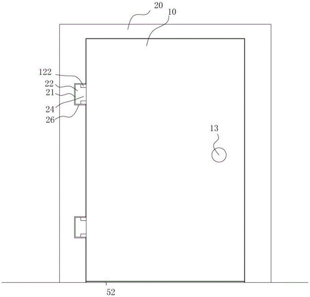
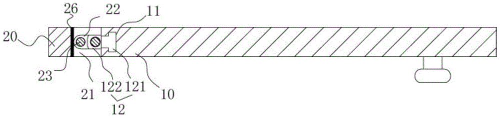
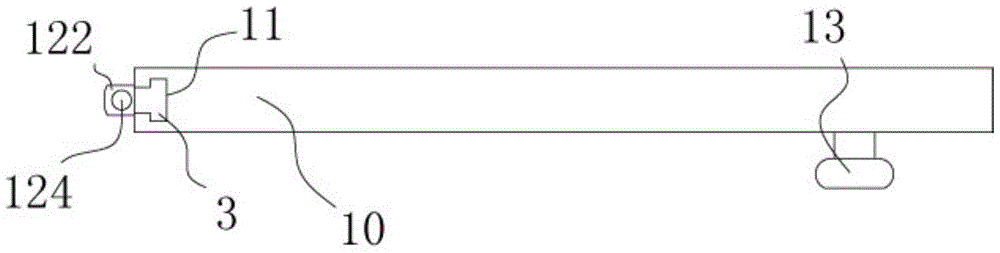
[0028] Example: see Figures 1 to 8 As shown, a door body structure with a bottom rolling barrier bar includes a door body 10 and a door frame 20, the door body 10 is located in the door frame 20, and the side wall of the door body 10 has a vertical convex groove 11. The convex-shaped parts 121 of at least two connecting blocks 12 are inserted into the convex-shaped grooves 11. The front part of the connecting block 12 has two hinge parts 122, and one inner side wall of the corresponding door frame 20 has a connecting groove 21 A hinge 22 is sleeved in the connection groove 21, and a hinge shaft 23 is inserted in the hinge 22. The two ends of the hinge shaft 23 are fixed on the upper and lower side walls of the connection groove 21. The middle part of the hinge 22 has Protruding part 24, the protruding part 24 is between the two hinge parts 122 of a connecting block 12, the protruding part 24 is connected with the hinge part 122 through the connecting shaft 25, and the handle ...


PUM


Abstract

The invention discloses a door body structure with a bottom rolling type baffle bar. The door body structure comprises a door body and a door frame, wherein the door body is arranged in the door frame; Vertical inverted-T-shaped grooves are formed in one side wall of the door body; inverted-T-shaped parts of at least two connection blocks are inserted into each inverted-T-shaped groove; two articulation parts are arranged at the front part of each connection block; connection grooves are formed in the corresponding inner side wall of the door frame; an articulation component is inserted into each connection groove; an articulation shaft is inserted into each articulation component; two ends of the articulation shaft are fixed on the upper side wall and the lower side wall of each connection groove; a protrusion part is arranged at the middle part of the articulation component and is located between the two articulation parts of each connection block; an elongated slot is formed in the bottom surface of the door body; a bottom connection block is inserted and fixed in the elongated slot; the cylindrical baffle bar is arranged in the elongated slot. The door body structure is convenient for connection; the door body can be mounted and dismounted repeatedly; meanwhile, the baffle bar at the bottom of the door body has the telescopic effect and is convenient to mount and dismount and can prevent outside dust from entering a room.

Description

[0001] Technical field: [0002] The invention relates to the technical field of door and window equipment, and more specifically relates to a door body structure with bottom rolling barrier strips. [0003] Background technique: [0004] The existing door body is installed in the door frame, which generally needs to be connected by a hinge between the door body and the door frame, which is not only troublesome to install, but also makes the connection side between the door body and the door frame uneven, affecting the overall appearance In addition, when the door body is disassembled, there is a bolt connection hole in the place where the hinge is disassembled. If it is reinstalled, it cannot be connected in the original bolt connection hole. It needs to find another part to connect, which will affect the reinstallation and affect the aesthetics. [0005] At the same time, there is a gap between the bottom edge and the bottom surface of the existing door body. Generally, in or...

Claims


Application Information

Patent Timeline
Patent Type & Authority Patents(China)
IPC IPC(8): E06B3/36E06B7/18E05D7/10E05D7/04
Inventor 张建勋候晓翠
Owner QINGDAO R & D INST XIAN JIAOTONG UNIV
Why Eureka
Try Eureka