Heat Exchanger

A heat exchanger and cooling fin technology, applied in the field of heat exchanger equipment, can solve the problems of easy corrosion, corrosion, and poor heat exchange effect of the heat exchanger, and achieve enhanced installation stability, firm insertion, and not easy to fall off Effect

Active Publication Date: 2017-12-15
浙江新金宸机械有限公司
View PDF1 Cites 2 Cited by
  • Summary
  • Abstract
  • Description
  • Claims
  • Application Information

AI Technical Summary

Problems solved by technology

[0004] The above-mentioned solution solves the problem that the surface of the existing heat exchanger is easily corroded to a certain extent, but the solution still exists: the bottom of the heat exchanger is rusted and corroded due to water accumulation at the bottom, and the heat exchange effect becomes poor, which seriously affects The service life of the heat exchanger and other issues

Method used


Image

  • Heat Exchanger
  • Heat Exchanger
  • Heat Exchanger

Examples


Embodiment 1

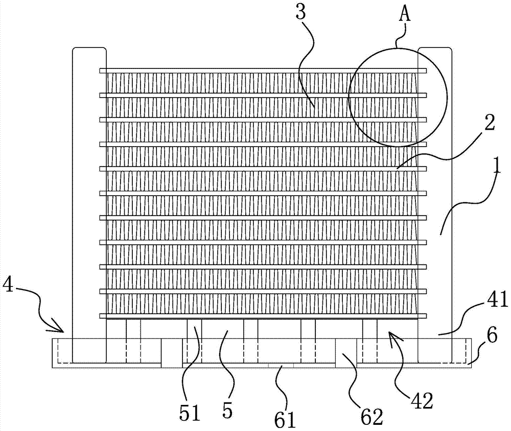
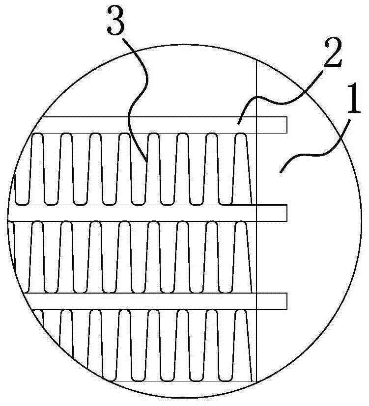
[0030] Such as Figure 1-2As shown, the heat exchanger includes two headers 1 parallel to each other and vertically arranged, and a number of flat tubes 2 parallel to each other and arranged horizontally are arranged between the headers 1, and each flat tube 2 is arranged along the The tubes 1 are arranged at intervals in the axial direction, and the two ends of the flat tubes 2 are respectively connected with the collecting tubes 1. There are also a number of cooling fins 3 in contact with the flat tubes 2 between the collecting tubes 1, and the flat tubes 2 are arranged horizontally and / or Or inclined to the horizontal plane, the lower end of the header 1 is provided with an overhead structure 4 that can prevent the flat tube 2 and cooling fins 3 from contacting with the accumulated liquid during work. Using this structure can make the bottom of the heat exchanger overhead to prevent The flat tube 2 is in contact with the radiating fin 3 and the effusion, which avoids the ru...

Embodiment 2

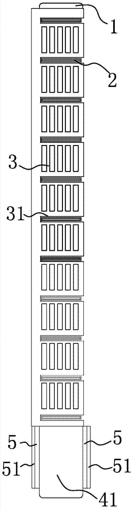
[0034] Such as image 3 As shown, the structure, principle and implementation steps of this embodiment are similar to those of Embodiment 1, the difference is that the heat dissipation fins 3 in this embodiment are made of metal sheets, and the heat dissipation fins 3 are vertically parallel to each other. Adjacently arranged and each cooling fin 3 crosses each flat tube 2 respectively, preferably, the flat tube 2 here is arranged transversely between two headers 1, and the cooling fin 3 is arranged vertically and intersects with the flat tube 2 Intersecting arrangement, wherein, the side of the cooling fins 3 here is provided with horizontal slots 31 corresponding to each flat tube 2 one by one, the flat tubes 2 are horizontally arranged and inserted in the horizontal slots 31, the depth of the horizontal slots 31 greater than the width of the flat tubes 2, that is, the flat tubes 2 here are arranged parallel to each other, and the cooling fins 3 are connected to each other t...

Embodiment 3

[0036] Such as Figure 4-10 As shown, the structure, principle and implementation steps of this embodiment are similar to those of Embodiment 1, the difference is that the heat dissipation fins 3 in this embodiment are made of metal sheets, and the heat dissipation fins 3 are vertically parallel to each other. Adjacently arranged and each cooling fin 3 crosses each flat tube 2 respectively, preferably, the flat tube 2 here is arranged transversely between two headers 1, and the cooling fin 3 is arranged vertically and intersects with the flat tube 2 Arranged crosswise, the sides of the cooling fins 3 are provided with inclined slots 32 corresponding to the flat tubes 2 one by one. The flat tubes 2 are arranged obliquely and inserted into the inclined slots 32. width, that is, the flat tube 2 here is set obliquely to the horizontal plane, so that the condensate can be discharged faster, and it is not easy to gather on the flat tube 2, and the cooling fins 3 are cross-connected ...


PUM


Abstract

The invention belongs to the technical field of heat exchanger equipment, and in particular relates to a heat exchanger. It solves the problems of easy corrosion of existing heat exchangers and the like. It includes two parallel and vertical collecting pipes, and a number of parallel and horizontal flat pipes are arranged between the collecting pipes. The flat pipes are distributed along the axial direction of the collecting pipe at intervals. It is connected with the collecting pipe, and there are several heat dissipation fins in contact with the flat pipes between the collecting pipes. The flat pipes are arranged horizontally or / or inclined to the horizontal plane. The fins are an overhead structure that avoids contact with effusions during work. The advantage of this heat exchanger is that the bottom of the heat exchanger can be elevated, and the liquid accumulation cavity of the bottom liquid collection plate can collect the discharge liquid, so as to achieve the purpose of anti-corrosion. When the through hole on the liquid collection plate is blocked, it can pass through the drain The liquid tank flows out, and the heat dissipation fins and flat tubes are firmly inserted, which is not easy to fall off, and the installation stability of the heat dissipation fins is enhanced.

Description

technical field [0001] The invention belongs to the technical field of heat exchanger equipment, and in particular relates to a heat exchanger. Background technique [0002] A heat exchanger is a device that transfers part of the heat of a hot fluid to a cold fluid, also known as a heat exchanger. Common heat exchangers have various forms, among which parallel flow heat exchangers are most widely used because of their compact structure and small size. A common parallel flow heat exchanger mainly includes a pair of headers that are parallel to each other and separated from each other. Several flat tubes that are connected to the inner chambers of the two headers and are parallel to each other are arranged between adjacent flat tubes. The fins in between, and the two side plates fixedly connected with the outer flat tubes through the fins, the header is provided with a number of holes for connecting the flat tubes, and the whole heat exchanger is a flat plate-like structure a...

Claims


Application Information

Patent Timeline
Patent Type & Authority Patents(China)
IPC IPC(8): F28D1/053F28F17/00F28F1/12
Inventor 董长盛李梁
Owner 浙江新金宸机械有限公司
Why Eureka
Try Eureka