Supercharge Your Innovation With Domain-Expert AI Agents!

Voltage step device and mining DC power supply detection device

A voltage step, DC power supply technology, applied in the field of electric power, can solve the problems of unsuitable mining DC power supply for testing, inability to automatic step jump, complicated test process, etc., to achieve compact structure, automatic step jump, simple effect

Active Publication Date: 2015-12-02
CHINA COAL TECH ENG GRP CHONGQING RES INST
View PDF10 Cites 10 Cited by
  • Summary
  • Abstract
  • Description
  • Claims
  • Application Information

AI Technical Summary

Problems solved by technology

However, at the present stage, the input AC power is generally adjusted manually in the test process of mine-used regulated power supply, instead of automatic step jump, so the test process is more complicated and the test efficiency is lower.
Chinese patent authorization announcement number CN202512147 discloses a step signal source, including a DC power supply unit, a voltmeter, a precision resistor network, etc. The generation of the step signal is realized by adjusting the two precision resistors in the precision resistor network , and the power supply of the connection signal source is a DC power supply, and the mine DC power supply test requires an AC power supply. Therefore, this step signal source is not suitable for the test of the mine DC power supply, and it also cannot automatically step jump

Method used


Image

  • Voltage step device and mining DC power supply detection device
  • Voltage step device and mining DC power supply detection device
  • Voltage step device and mining DC power supply detection device

Examples


specific Embodiment 1

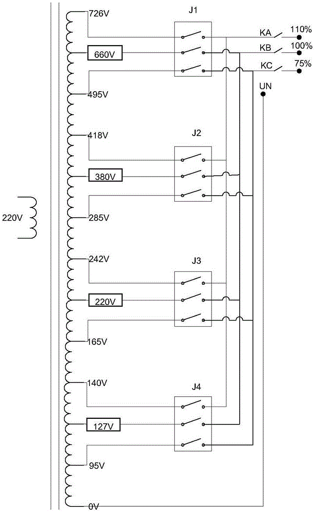
[0027] In the voltage step device in this embodiment, the control switch includes a gear control switch for realizing the corresponding gear control and a grade control switch for realizing the grade switching of each gear, the gear control switch is a relay, and the grade control switch is electronic switch. Such as image 3 As shown, since the regulated power supply under test is generally powered by commercial power, the input power supply of the voltage step device in this embodiment uses a nominal voltage of 220V, and different transformer windings are used to output the corresponding ranges, which are divided into 127V, 220V, There are four gears of 380V and 660V, and the corresponding gear control switches J4, J3, J2, and J1 are used to control the conduction between each gear, and the corresponding pins P00-P03 of the controller are controlled by J4, J3, J2, and J1. connection, such as Figure 7 As shown; each gear is divided into three levels of output: 75%, 100%, a...

specific Embodiment 2

[0030] Compared with the first embodiment, the voltage step device in this embodiment differs in that the output voltage branches corresponding to the taps of each level of each gear are controlled by independent control switches, that is, the three levels of the 127V gear use K41~K43 respectively Control, the three levels of the 220V gear are controlled by K31~K33 respectively, the three levels of the 380V gear are controlled by K21~K23 respectively, and the three levels of the 660V gear are controlled by K11~K13 respectively. The control in this embodiment The switch can be a relay, or an electronic switch of a similar device such as a MOSFET tube or an IGBT. In this embodiment, if the voltage of 220V gear is to be used to realize the step jump of 75% Ue → 100% Ue → 110% Ue, the controller controls the corresponding level control switches K33, K32, K31 to sequentially switch the lead Pass.


PUM


Abstract

The invention provides a voltage step device and a mining DC power supply detection device. The voltage step device comprises a controller and a transformer the primary side of which is connected with an AC input power supply, the secondary side of the transformer is provided with taps, and the taps are provided with output voltage branch circuits in different grades which are divided according to percentages of an output voltage. The output voltage branch circuits are provided with switches, and the controller controls the switches to be turned on and / or off so that step jumps of the output voltage are generated. The switches disposed on the branch circuits are controlled through the controller, free switching on the output voltage is performed as needed, automatic step jumps of the voltage are achieved, and test efficiency is improved; and the voltage step device has the advantages of the simple principle, compact structure and high practicability.

Description

technical field [0001] The invention relates to the field of electric power, in particular to a voltage step device and a mining DC power supply detection device. Background technique [0002] Mining DC power supply is a special power supply. The Coal Mine Special Equipment Standardization Technical Committee of the Ministry of Coal Industry of the People's Republic of China proposed the coal industry standard -- MT / T408-1995 "DC Stabilized Power Supply for Coal Mine" for its basic performance and the test process are specified in detail, among which the source effect is a particularly important performance index. The standard describes its experimental device and test procedures. The test device includes a voltage step for applying a step voltage to the DC power supply under test. Step device, the power input end of the voltage step device is also connected with an AC voltage stabilizer and voltage regulator, the output end of the DC power supply under test is connected wit...

Claims


Application Information

Patent Timeline
IPC IPC(8): G01R1/28G01R31/40
Inventor 石发强孔令刚孙健黄显汤
Owner CHINA COAL TECH ENG GRP CHONGQING RES INST
Features
  • R&D
  • Intellectual Property
  • Life Sciences
  • Materials
  • Tech Scout
  • Unparalleled Data Quality
  • Higher Quality Content
  • 60% Fewer Hallucinations
Learn More