Continuous wave radar Doppler echo detection method

A technology of Doppler echo and detection method, applied in the field of space microwave remote sensing, can solve problems such as inability to detect echo signals, signal detection problems, and echo signal detection problems.

Active Publication Date: 2015-12-02
XIAN INSTITUE OF SPACE RADIO TECH
View PDF4 Cites 18 Cited by
  • Summary
  • Abstract
  • Description
  • Claims
  • Application Information

AI Technical Summary

Problems solved by technology

[0003] In order to obtain high speed measurement accuracy and light weight requirements of the system, the continuous wave radar is used to measure the beam direction velocity during the landing process. However, since the continuous wave radar adopts the principle of transmitting and receiving at the same time, the existence of the direct wave leakage signal will directly affect the target echo. In the design of the speed sensor, a high isolation design is carried out for the transceiver antenna, and the video cancellation technology is used to further reduce the influence of the leaked signal on the signal detection, but the residual signal leaked in the signal detection port and the vibration of the transceiver antenna The spectral broadening component of the leaked signal caused by phase jitter in the environment brings difficulties to the detection of the signal; at the same time, due to the poor anti-jamming ability of the continuous wave system radar, the clutter on the power supply will be reflected on the echo signal, so the clutter of the system Scatter and interference also bring difficulties to echo signal detection
[0004] At present, the existing literature mainly uses the analog frequency tracking loop to track and detect the echo signal of the continuous wave speed measuring radar, and can only process the echo signal whose speed is greater than a certain range, that is, the Doppler frequency. This method cannot detect more than zero Echo signals near the Puller while the analog frequency tracking loop is susceptible to interfering signals

Method used


Image

  • Continuous wave radar Doppler echo detection method
  • Continuous wave radar Doppler echo detection method
  • Continuous wave radar Doppler echo detection method

Examples


Embodiment Construction

[0041] Specific embodiments of the present invention will be further described in detail below in conjunction with the accompanying drawings.

[0042] Spectrum detection is to extract the complete and unaffected spectrum of the lunar surface target, which is the key to normal speed measurement.

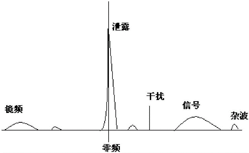
[0043] Such as figure 1 Shown is the schematic diagram of the continuous wave echo spectrum characteristics, from figure 1 It can be seen that the target echo signal in the continuous wave speed measurement system is mainly affected by four factors: image frequency and harmonics, interference, clutter, direct wave leakage + phase noise, and power supply ripple.

[0044]The image frequency and harmonics are mainly due to the real-time adjustment of the receiver AGC in each measurement cycle during the actual measurement process, and the saturation of the time-domain IQ baseband signal due to untimely adjustment in individual cycles; its characteristic is that it is based on the real e...


PUM


Abstract

A continuous wave radar Doppler echo detection method comprises the steps: (1) after a baseband signal is sampled, performing N-point FFT operation to obtain a power spectrum curve of a sampling signal, (2) according to a result of gain control (AGC) of a last measurement period, calculating an SNR (signal to noise ratio) threshold of echo detection of this period, (3) judging a working mode, wherein, in a near-zone mode, echo spectrum searching is performed according to a near-zone mode zone division, and, in a far-zone mode, the echo spectrum searching is performed according to a far-zone mode zone division, (4) calculating a speed value according to a detected spectrum position, (5) switching a working mode of a next measurement period according to a speed result, and (6) performing calculation of a gain control (AGC) value according to an acquired time domain signal, and taking an AGC control result as a calculation basis of the SNR threshold of the next period. The method improves the success rate of echo signal detection, and improves the continuous wave radar anti-interference capability.

Description

technical field [0001] The invention relates to a radar Doppler echo detection method, in particular to a continuous wave radar Doppler echo detection method, which belongs to the field of space microwave remote sensing technology. Background technique [0002] The continuous wave velocity radar is a key single unit in the lunar deep space exploration and landing project. It provides accurate satellite velocity information for the satellite guidance, navigation and control systems, thereby ensuring the safety of the landing. The measurement accuracy of the continuous wave speed measuring radar is high, and the Doppler frequency of the beam center is calculated by using the Doppler beam center calculation method of the high-precision surface target echo and the Doppler spectrum of the opposite target. In addition, continuous wave speed measuring radar has broad application prospects in missile guidance, carrier-based aircraft, and UAV take-off and landing. [0003] In order ...

Claims


Application Information

Patent Timeline
Patent Type & Authority Applications(China)
IPC IPC(8): G01S7/41
CPCG01S7/41
Inventor 牛文博谭小敏党红杏王科张爱军孙嘉刘瑞东薛强李拴劳郭语贾建超
Owner XIAN INSTITUE OF SPACE RADIO TECH
Why Eureka
Try Eureka