Rotating electrical machine
A rotary motor and rotary drive technology, applied in electrical components, electromechanical devices, electric components, etc., can solve the problems of increased torque loss and decreased efficiency of the rotary motor, and achieves the advantages of suppressing the increase in manufacturing cost, simple structure, and efficient cooling. Effect
- Summary
- Abstract
- Description
- Claims
- Application Information
AI Technical Summary
Problems solved by technology
Method used
Image

Examples
Embodiment approach 1
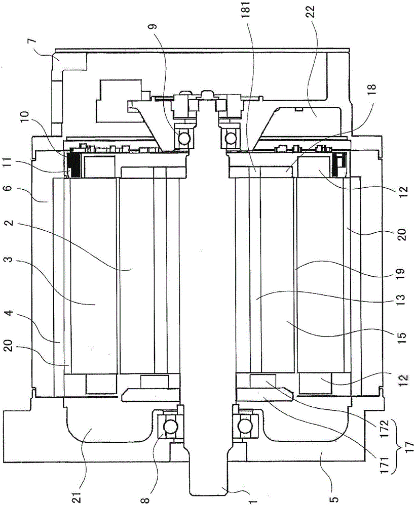
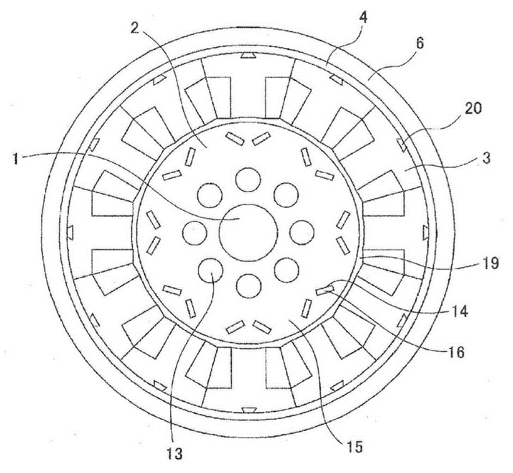
[0029] based on figure 1 and figure 2 A rotating electric machine according to Embodiment 1 of the present invention will be described. figure 1 is an axial sectional view showing the rotating electric machine according to Embodiment 1 of the present invention, figure 2 is a radial sectional view. In addition, in all the following drawings, the same code|symbol is attached|subjected to the same part in a figure. The rotating electric machine according to Embodiment 1 includes: a shaft 1 for rotational driving; a rotor 2 provided on the peripheral surface of the shaft 1; a stator 3 disposed opposite to the outer peripheral surface of the rotor 2; bearings supporting both ends of the shaft 1, and housing The casing of the rotor 2 and the stator 3.
[0030] figure 1 Among them, the housing is composed of three frames, the front frame 5 , the middle frame 6 and the rear frame 7 . The ring-shaped divided stator 3 is fitted to a cylindrical iron frame 4 , and the iron frame ...
Embodiment approach 2
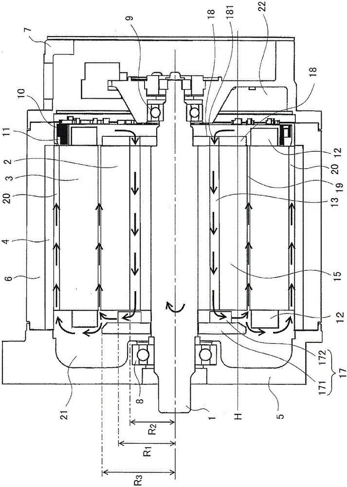
[0049] In Embodiment 2 of the present invention, using Figure 4 ~ Figure 11 Various modified examples for improving the cooling effect of the cooling mechanism for the rotating electric machine described in the first embodiment will be described. In addition, since the overall configuration of the rotating electric machine according to Embodiment 2 is the same as that of Embodiment 1, description thereof will be omitted (see figure 1 ).
[0050] As a modified example for increasing the flow rate of the circulating air flow, such as Figure 4 As shown, a plurality of rotor outer peripheral grooves 23 penetrating in the axial direction are formed on the outer peripheral surface of the rotor 2 . As a result, the gap 19 between the rotor 2 and the stator 3 and the rotor outer circumferential groove 23 become a ventilation path outside the rotor 2, and the flow rate of the circulating air flow outside the rotor 2 increases, thereby improving the cooling effect.
[0051] In addi...
Embodiment approach 3
[0061] Figure 12 The load-side end plate of the electric rotating machine concerning Embodiment 3 of this invention is shown, (a) is a top view, (b) is an axial cross-sectional view. In the figure, H represents the oil level height of the cooling oil. In addition, since the overall configuration of the rotating electrical machine according to Embodiment 3 is the same as that of Embodiment 1, description thereof will be omitted (see figure 1 ).
[0062] The spray generating means only needs to have the function of splashing the cooling oil stored in the casing with the rotation of the rotor 2, so it may be any one of the load side end plate 17 and the non-load side end plate 18, or this may be used. two. That is, the recessed portion for improving the cooling oil splashing ability may be provided on either one of the load-side end plate 17 and the non-load-side end plate 18 , or may be provided on both of them. In Embodiment 1 and Embodiment 2 above, the non-load-side end ...
PUM
 Abstract
Description
Claims
Application Information