Oral cavity scanner

A technology for scanners and oral cavity, which is applied in the field of oral scanners, can solve problems such as severe shaking, and achieve the effect of quality assurance

Active Publication Date: 2015-12-09
QISDA OPTRONICS (SUZHOU) CO LTD +1
View PDF9 Cites 13 Cited by
  • Summary
  • Abstract
  • Description
  • Claims
  • Application Information

AI Technical Summary

Problems solved by technology

[0004] Due to the particularity of real-time scanning in the mouth, the oral scanner needs to be able to be placed in the oral cavity, and the length of entering the oral cavity is too long, which will cause severe shaking. The length of entering the oral cavity is too short, and the doctor's hand is easy to touch the patient's mouth. Therefore, the length of the oral scanner into the oral cavity cannot be too long or too short

Method used


Image

  • Oral cavity scanner
  • Oral cavity scanner
  • Oral cavity scanner

Examples


Embodiment Construction

[0020] In order to have a further understanding of the purpose, structure, features, and functions of the present invention, the following detailed descriptions are provided in conjunction with the embodiments.

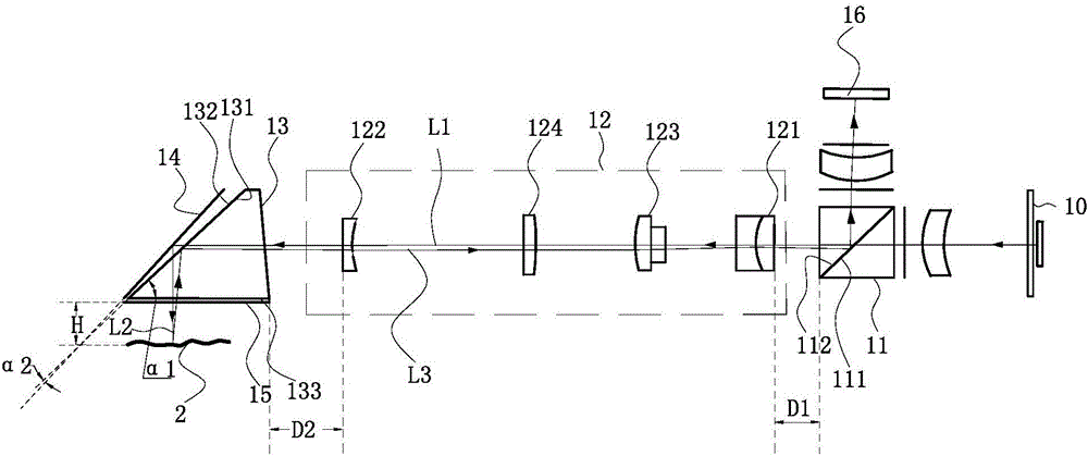
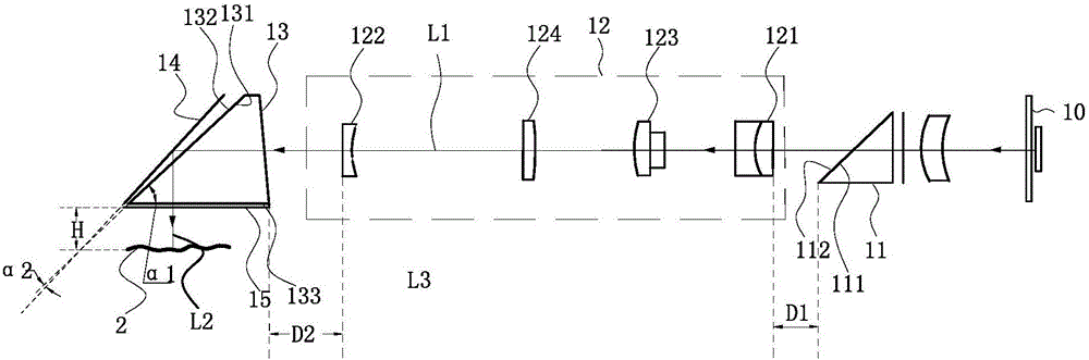
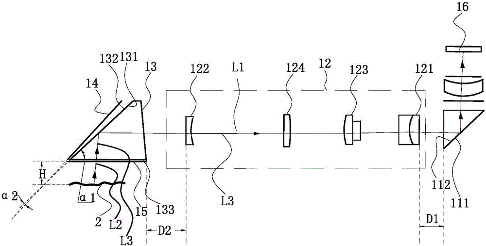
[0021] figure 1 A schematic diagram of an oral scanner provided by an embodiment of the present invention; figure 2 for figure 1 A schematic diagram of the projection light path of the oral scanner shown; image 3 for figure 1 A schematic diagram of the imaging optical path of the dental scanner shown.

[0022] Such as Figure 1 to Figure 3 As shown, the oral scanner 1 includes: an image capturing device 16 , a first polarizing element 11 , a second polarizing element 13 , a mirror 14 , a quarter-wave plate 15 and a projection and imaging lens set 12 . The image capture device 16 is used to capture an image of the object under test 2 , preferably, the image capture device 16 may be a Charge-coupled Device (CCD). The first polarizing element 11 includes a first ...


PUM


Abstract

The invention provides an oral cavity scanner. The oral cavity scanner comprises an image capture device, a first polarization element, a second polarization element, a reflector, a quarter-wave plate and a projection and image acquisition lens set. The projection and image acquisition lens set comprises a first lens and a second lens. When entering a first face, a projection light beam penetrates through the first face and a second face in sequence, enters a third face through the first lens and the second lens in sequence after coming out of the second face, then enters the reflector after penetrating through the third face and a fourth face in sequence and penetrates through the fourth face, the third face and the quarter-wave plate in sequence after being reflected by the reflector to form a first light beam; the first light beam enters an object to be measured and penetrates through the quarter-wave plate after being reflected by the object to be measured to form an image acquisition light beam; the image acquisition light beam enters the third face, enters the projection and image acquisition lens set after being reflected by the third face, enters the second face after passing through the second lens and the first lens in sequence and enters the image capture device after being reflected by the second face so that the image capture device can acquire an image of the object to be measured.

Description

technical field [0001] The invention relates to the field of medical equipment, in particular to an oral cavity scanner. Background technique [0002] In the process of clinical oral diagnosis and restoration, oral impression is an important source of information storage, and almost every patient needs to take one or more impressions. By comparing multiple models before, during, and after treatment, doctors can understand the effect of treatment and improve the accuracy of inspection, diagnosis, and treatment. Dental technicians also need to determine the shape of denture restorations based on impressions. [0003] At present, the digital impression technology with easy operation, high precision and convenient storage has attracted more and more attention from the stomatology field, and more and more scholars and companies have invested a lot of energy and financial resources in researching it. The methods of obtaining digital impressions are divided into two categories acc...

Claims


Application Information

Patent Timeline
Patent Type & Authority Applications(China)
IPC IPC(8): A61B1/247A61B1/04A61B1/06A61C9/00
Inventor 林明坤
Owner QISDA OPTRONICS (SUZHOU) CO LTD
Why Eureka
Try Eureka