Large-flow compressed air and foam mixing device

A technology of compressed air foam and mixing device, used in fire rescue and other directions, can solve the problems of affecting the spray distance of compressed gas foam, insufficient to ensure full mixing of gas and liquid, affecting the fire extinguishing effect of fire extinguishing device, etc., to achieve good atomization effect and kinetic energy. The effect of large, increased blending range

Active Publication Date: 2015-12-09
CHINA PETROLEUM & CHEM CORP QINGDAO RES INST OF SAFETY ENG +1
View PDF5 Cites 5 Cited by
  • Summary
  • Abstract
  • Description
  • Claims
  • Application Information

AI Technical Summary

Problems solved by technology

[0002] At present, compressed air foam fire extinguishing devices at home and abroad are mainly used in fire trucks, foam guns and other fire extinguishing devices. The flow rate is relatively small, and it is mainly used to put out general-scale fires. The gas-liquid mixing device is relatively simple, such as wire mesh, orifice plate etc. These fluid spoilers have a large resistance to the fluid, which affects the spray distance of the compressed gas foam
When the flow rate of the foam mixture increases, the structure of the existing gas-liquid mixing device is simple, which is not enough to ensure that the gas-liquid is fully mixed, thereby affecting the quality of foam foaming, and further affecting the fire extinguishing effect of the fire extinguishing device

Method used


Image

  • Large-flow compressed air and foam mixing device
  • Large-flow compressed air and foam mixing device
  • Large-flow compressed air and foam mixing device

Examples


Embodiment Construction

[0019] The specific embodiment of the present invention will be further described below in conjunction with accompanying drawing and specific embodiment:

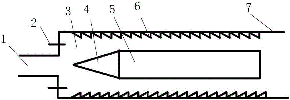
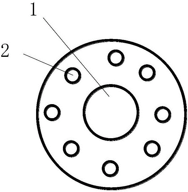
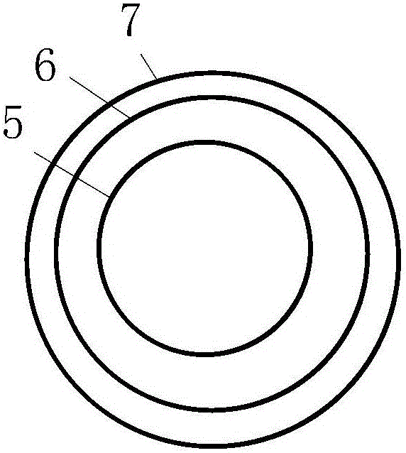
[0020] Such as Figure 1-3 As shown, a large-flow compressed air foam mixing device includes a foam mixture nozzle 1, the foam mixture nozzle 1 is connected with a mixing chamber 3, and the mixing chamber 3 is provided with a conical spoiler 4 and a conical spoiler 4 The cone angle is 20°, and the distance between the tip of the cone and the foam mixture nozzle 1 does not exceed the radius of the foam mixture nozzle 1. The end of the conical spoiler 4 is connected with a secondary spoiler 5, and the cylinder diameter of the secondary spoiler 5 is equal to the diameter of the cone of the conical spoiler 4. The inside of the tube wall of the mixing chamber 3 is provided with an inner wall surface boss 6, the inner wall surface boss 6 is a right triangle, and the long right angle side is fixedly connected with the inner wall ...


PUM

PropertyMeasurementUnit
Cone angleaaaaaaaaaa

Abstract

The invention discloses a large-flow compressed air and foam mixing device and relates to the technical field of compressed air and foam mixing devices. The large-flow compressed air and foam mixing device solves the problem that because existing air-liquid mixing devices are simple in structure and air and liquid cannot be fully mixed when the flow of foam-mixed liquid is increased, the foaming quality is influenced. The large-flow compressed air and foam mixing device comprises a foam-mixed liquid nozzle. The foam-mixed liquid nozzle is connected with a mixing cavity, a conical turbulence device is arranged in the mixing cavity, the tail end of the conical turbulence device is connected with a secondary turbulence device, inner wall surface bosses are arranged on the inner side of the pipe wall of the mixing cavity, the arrangement length of the inner wall surface bosses on the inner wall surface of the mixing cavity is equal to the total length of the conical turbulence device and the secondary turbulence device, and air inlet pipes are uniformly arranged on the end surface, connected with the foam-mixed liquid nozzle, of the mixing cavity.

Description

technical field [0001] The invention relates to the technical field of compressed air foam mixing devices, in particular to a large-flow compressed air foam mixing device. Background technique [0002] At present, compressed air foam fire extinguishing devices at home and abroad are mainly used in fire trucks, foam guns and other fire extinguishing devices. The flow rate is relatively small, and it is mainly used to put out general-scale fires. The gas-liquid mixing device is relatively simple, such as wire mesh, orifice plate etc. These fluid spoilers have relatively large resistance to the fluid, which affects the spraying distance of the compressed gas foam. When the flow rate of the foam mixture increases, the existing gas-liquid mixing device has a simple structure, which is not enough to ensure sufficient gas-liquid mixing, thereby affecting the foaming quality and further affecting the fire extinguishing effect of the fire extinguishing device. Contents of the inven...

Claims


Application Information

Patent Timeline
IPC IPC(8): A62C5/02
Inventor 郎需庆牟小冬张卫华
Owner CHINA PETROLEUM & CHEM CORP QINGDAO RES INST OF SAFETY ENG
Why Eureka
Try Eureka