Automatic rotating sprayer

An automatic rotating and rotating head technology, applied in the field of atomization, can solve the problems of the heavy weight of the rotating head and the poor atomization effect of the atomizing nozzle, and achieve the effect of reducing the weight, reducing the resistance and increasing the atomization area.

Active Publication Date: 2017-07-28
BEIJING CHINA SCI PURIFICATION ECO TECH
View PDF6 Cites 4 Cited by
  • Summary
  • Abstract
  • Description
  • Claims
  • Application Information

AI Technical Summary

Problems solved by technology

[0005] Therefore, the technical problem to be solved by the present invention is that the atomization effect of the atomizing nozzle in the prior art is poor and the weight of the rotating head is large

Method used


Image

  • Automatic rotating sprayer
  • Automatic rotating sprayer
  • Automatic rotating sprayer

Examples


Embodiment 1

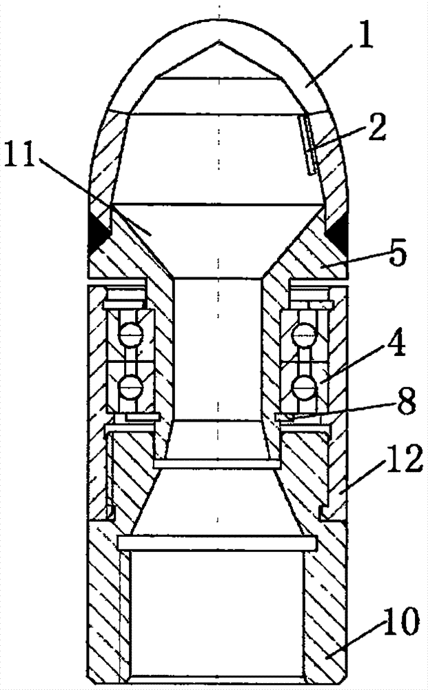
[0056] Such as figure 1 As shown, the embodiment of the present invention provides an automatic rotary spray head, including

[0057] stator;

[0058] The rotary head 1 is rotatably connected to the stator, has a fluid chamber, at least one fluid inlet 11 and several fluid outlets communicated with the fluid chamber;

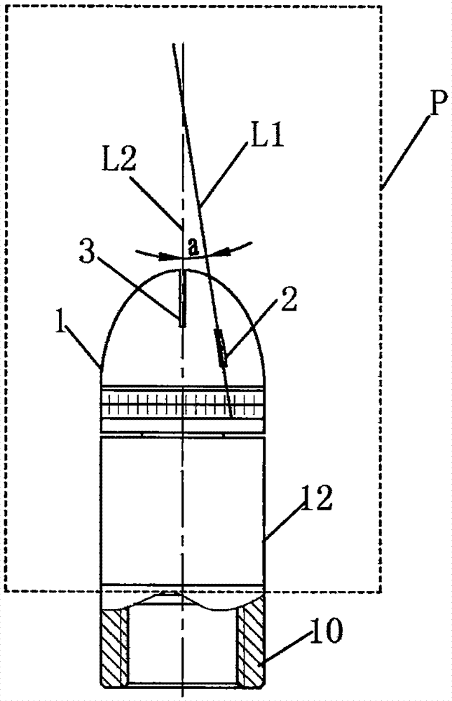
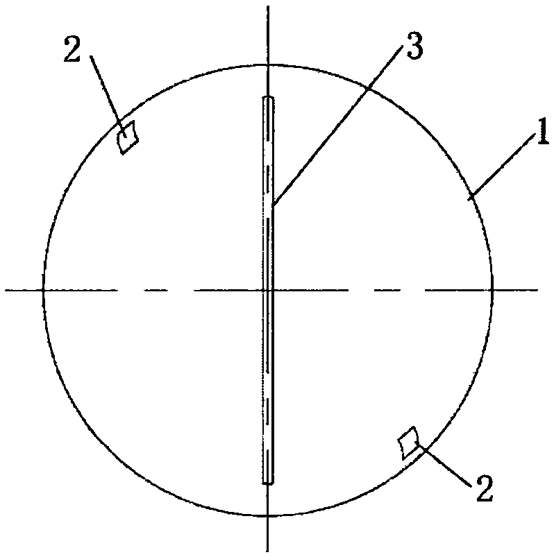
[0059] The power slit 2, at least one, is arranged on the rotating head 1 and communicates with the fluid chamber; the projection line L1 of its axis on the longitudinal projection plane P, and the projection of the axis of the height direction of the rotating head 1 on the longitudinal projection plane P Line L2 does not coincide, as figure 2 shown.

[0060] The above-mentioned automatic rotary spray head only needs to set up a power slit 2 on the rotary head 1, the projection line L1 of the axis of the power slit 2 on the longitudinal projection plane P, and the axis of the height direction of the rotary head 1 on the longitudinal projection plane The pro...


PUM


Abstract

The invention discloses an automatic rotating sprayer which comprises a stator, a rotating head rotationally connected to the stator, and at least one power slit. The rotating head is provided with a fluid cavity, at least one fluid inlet and multiple fluid outlets, wherein the fluid inlet and the fluid outlets communicate with the fluid cavity. The power slits are arranged on the rotating head and communicate with the fluid cavity, the projection line, on the longitudinal projection face, of the axis of the power slit does not coincide with the projection line, on the longitudinal projection face, of the axis in the height direction of the rotating head, so that when a solution in the fluid cavity is sprayed out from the power slit, impact force is generated on the rotating head and is then converted into torque driving the rotating head to rotate, the solution is in the shape of fog curtains when sprayed out from the power slit, the fog curtains can be better atomized under the rotation of the rotating head, and therefore the atomization effect of the sprayer is improved, and the weight of the sprayer is reduced; and meanwhile, the resistance exerted on the solution is low when the solution is sprayed out of the power slit, relatively small kinetic energy is lost, and the injection range of the atomized solution is longer.

Description

technical field [0001] The invention relates to the field of atomization technology, in particular to an automatic rotating nozzle. Background technique [0002] The structure of the commonly used atomizing nozzle in the prior art mainly includes a fixed nozzle body. The nozzle body has a spiral fluid chamber inside, and the nozzle installed at the outlet of the nozzle body. Atomized under the action of centrifugal force and sprayed out through the nozzle. However, for the nozzle with this structure, when the fluid rotates in the fluid chamber, most of its kinetic energy is absorbed by the nozzle body, which reduces the atomization kinetic energy of the nozzle and shortens the atomization distance. [0003] Chinese patent document CN104741258A discloses an atomizing nozzle, including a rotating head with a smooth outer wall, a direct-injection fan nozzle arranged on the end of the rotating head, a wide-angle power nozzle symmetrically arranged on both radial sides of the ro...

Claims


Application Information

Patent Timeline
Patent Type & Authority Applications(China)
IPC IPC(8): B05B3/04B05B15/00
CPCB05B3/04B05B15/00
Inventor 尹应武李大川赵琰琰刘文恒何荣华尹政清潘小勇黄仁兵韩田田陈红樱任毅华
Owner BEIJING CHINA SCI PURIFICATION ECO TECH
Why Eureka
Try Eureka