A membrane module with a filler inside

A technology of filler and membrane module, which is applied in the field of water purification, can solve the problems of increasing energy consumption, membrane pollution, and reducing the service life of membranes, so as to achieve the effect of reducing pollution load

Active Publication Date: 2018-02-27
湖州鼎泰软片膜科技有限公司
View PDF5 Cites 0 Cited by
  • Summary
  • Abstract
  • Description
  • Claims
  • Application Information

AI Technical Summary

Problems solved by technology

[0002] As a relatively new technology developed in modern times, the membrane process is suitable for wastewater treatment and filtration. It has the advantages of simple structure, low cost, and small footprint; Serious membrane fouling is caused, which reduces the flux of membrane filtration, increases energy consumption and reduces the service life of the membrane itself, which is a major bottleneck restricting the development of membrane technology.

Method used


Image

  • A membrane module with a filler inside
  • A membrane module with a filler inside
  • A membrane module with a filler inside

Examples


Embodiment 1

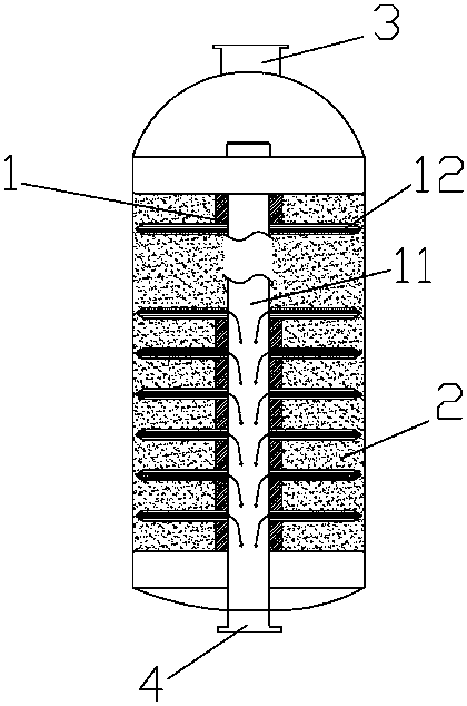
[0031] Embodiment 1: A membrane module with a filler inside, a membrane element 1 is arranged in the membrane module, a filling space is arranged in the membrane module, and activated carbon particle filler 2 is filled in the filling space.

[0032] The membrane module adopts a terminal filtration structure, and the membrane module is provided with a feed inlet 3 and a clean water outlet 4 .

[0033] The membrane element 1 is a plurality of membranes 12 fixed on the flow column 11. The membrane 12 includes an outer filter side and an inner permeate side. The permeate side communicates with the flow column 11, and the permeate flows out from the flow column 11. ; The filling space is the gap between the filter side of the membrane element and the shell of the membrane module, and the filling space is filled with activated carbon particles.

Embodiment 2

[0034] Embodiment 2: A membrane module with a filler inside, a membrane element 1 is arranged in the membrane module, a filling space is arranged in the membrane module, and a filler 2 mixed with activated carbon particles and porous resin particles is filled in the filling space .

[0035] The membrane module adopts a terminal filtration structure, and the membrane module is provided with a feed inlet 3 and a clean water outlet 4 .

[0036] The membrane element 1 is a plurality of membranes 12 fixed on the flow column 11. The membrane 12 includes an outer filter side and an inner permeate side. The permeate side communicates with the flow column 11, and the permeate flows out from the flow column 11. ; The filling space is the gap between the filter side of the membrane element and the housing of the membrane module, and the filling space is filled with fillers.

Embodiment 3

[0037] Embodiment 3: A membrane module with a filler inside. A membrane element 1 is arranged in the membrane module, a filling space is arranged in the membrane module, and a natural zeolite particle filler 2 is filled in the filling space.

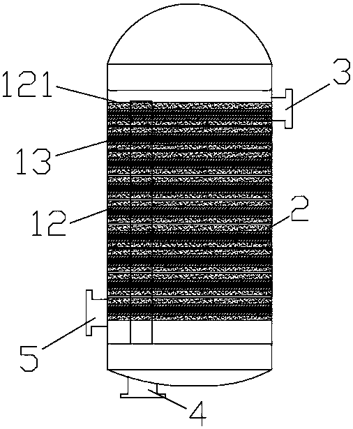
[0038] The membrane module adopts a cross-flow filtration structure, and the membrane module is provided with a feed inlet 3 , a clean water outlet 4 and a discharge outlet 5 .

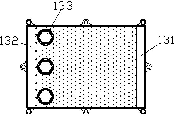
[0039] The membrane element is an assembly consisting of several sets of flow channel plates 13 and diaphragms 12 connected to the flow channel plates. The flow channel plates 13 are provided with raw material liquid inlets 131 and circulating liquid outlets 132. A permeate outlet 133 is provided.

[0040] The surface of the diaphragm 12 is provided with a filter screen 121, and there is no opening between the filter screen 121 and the surface of the diaphragm 12 except the pores of the filter screen 121. The filter screen 121 and the surface of the diaphragm 12...


PUM


Abstract

The invention relates to a membrane module with filler inside, belonging to the technical field of water purification. The invention relates to a membrane module with filling inside. The membrane element is arranged inside the membrane module, and a filling space is arranged inside the membrane module. The filling space is filled with granular filler. The membrane module effectively reduces the pollution load of the membrane itself, and has the effect of cleaning the pollution on the surface of the membrane during filtration.

Description

technical field [0001] The invention relates to the technical field of water purification, in particular to a membrane module with a filler inside. Background technique [0002] As a relatively new technology developed in modern times, the membrane process is suitable for wastewater treatment and filtration. It has the advantages of simple structure, low cost, and small footprint; Serious membrane fouling is caused, which reduces the flux of membrane filtration, increases energy consumption and reduces the service life of the membrane itself, which is a major bottleneck restricting the development of membrane technology. Contents of the invention [0003] The purpose of the present invention is to solve the above problems and provide a membrane module that can effectively reduce the pollution load on the membrane surface and has cleaning effect on the pollution on the membrane surface during filtration. [0004] The technical scheme that the present invention solves the a...

Claims


Application Information

Patent Timeline
Patent Type & Authority Patents(China)
IPC IPC(8): B01D65/04C02F9/02
Inventor 魏新时魏颖张一国
Owner 湖州鼎泰软片膜科技有限公司
Why Eureka
Try Eureka