Automatic material feeding and discharging device
An automatic loading and unloading and unloading technology, which is applied in the direction of operating devices, forging/pressing/hammer devices, metal processing equipment, etc., can solve the problems of high labor intensity for workers, difficulty in automatic loading and unloading of round tube materials, and harsh working environment and other issues, to achieve the effect of broad market application prospects
- Summary
- Abstract
- Description
- Claims
- Application Information
AI Technical Summary
Problems solved by technology
Method used
Image

Examples
Embodiment 1
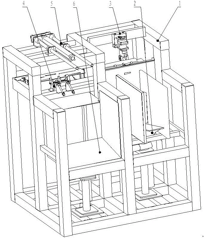
[0024] refer to figure 1 , an automatic loading and unloading device of the present invention comprises: a frame 1, a feeding mechanism 2, a reversing mechanism 3, a conveying and buffering mechanism 4, a feeding mechanism 5, and a blanking mechanism 6;
[0025] The frame 1 is made of overlapping aluminum profiles, the feeding mechanism 2 is located at the rear lower half of the feeding side of the frame, the reversing mechanism 3 is fixed at the front upper half of the feeding side of the frame, and the conveying and buffering mechanism 4 is fixed on the rack 1, and spans the feeding side and the unloading side of the rack. The conveying and buffering mechanism 4 contains a conveying mechanism and a buffering mechanism, the conveying mechanism is located below the reversing mechanism 3, the top of the buffering mechanism is a feeding mechanism 5, and the unloading mechanism 6 is fixed on the lower half of the frame unloading side, and is located at the bottom of the buffering...
PUM
 Abstract
Description
Claims
Application Information
 - R&D
- Intellectual Property
- Life Sciences
- Materials
- Tech Scout
- Unparalleled Data Quality
- Higher Quality Content
- 60% Fewer Hallucinations
Browse by: Latest US Patents, China's latest patents, Technical Efficacy Thesaurus, Application Domain, Technology Topic, Popular Technical Reports.
© 2025 PatSnap. All rights reserved.Legal|Privacy policy|Modern Slavery Act Transparency Statement|Sitemap|About US| Contact US: help@patsnap.com