High-precision voltage regulation type constant current source system suitable for strong inductive load

A technology of inductive load and constant current source, which is applied in the direction of control system, DC motor speed/torque control, electrical components, etc., can solve the problem of not being able to perfectly adapt to inductive loads, increasing the high-frequency phase shift of the feedback loop, and the accuracy level cannot be achieved Achieve and other problems, achieve the effect of avoiding the reduction of constant current control accuracy, reducing noise crosstalk, and broad market application prospects

Pending Publication Date: 2020-04-24
ZHEJIANG SCI-TECH UNIV
View PDF1 Cites 1 Cited by
  • Summary
  • Abstract
  • Description
  • Claims
  • Application Information

AI Technical Summary

Problems solved by technology

In addition, most precision constant current sources on the market cannot perfectly adapt to inductive loads
Its accuracy class does not match its precision when carrying inductive loads
Strong inductive loads will cause system instability due to current hysteresis. The reason is that the voltage at the reverse input terminal of the operational amplifier also lags, which increases the high-frequency phase shift of the feedback loop and leads to self-excited oscillation. The ex

Method used


Image

  • High-precision voltage regulation type constant current source system suitable for strong inductive load
  • High-precision voltage regulation type constant current source system suitable for strong inductive load
  • High-precision voltage regulation type constant current source system suitable for strong inductive load

Examples


Embodiment 1

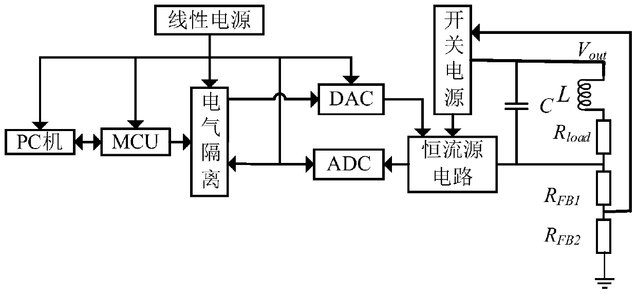
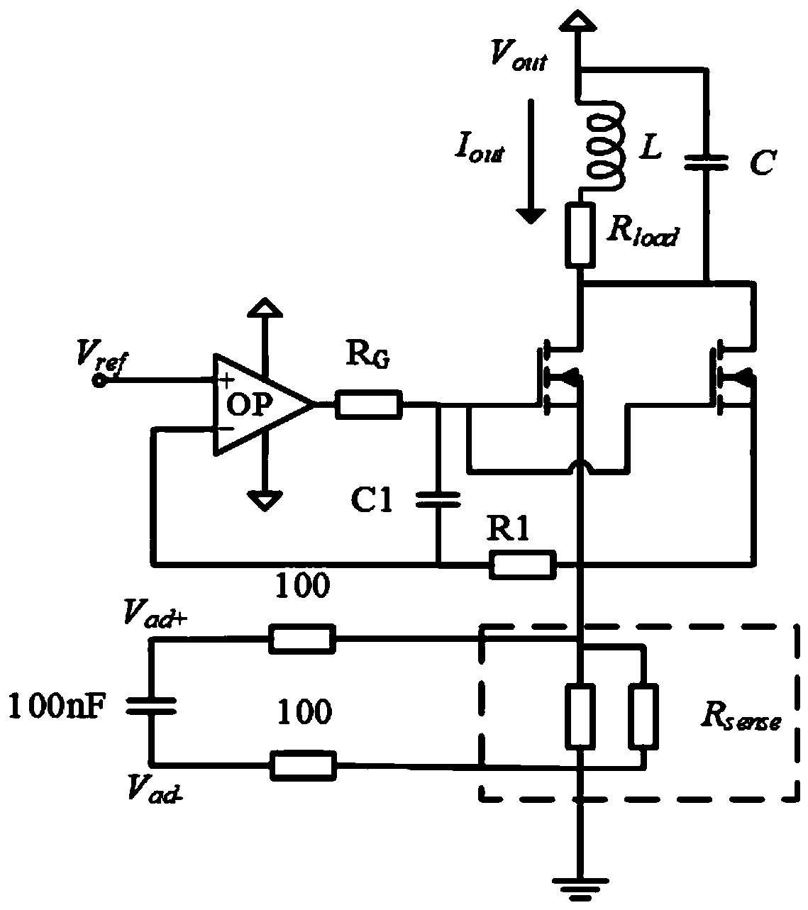
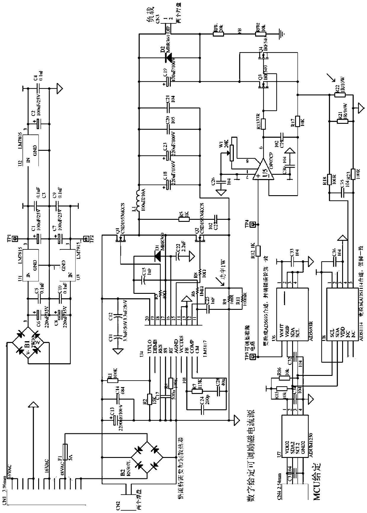
[0029] like Figure 1-5 As shown, the high-precision voltage-regulating constant-current source system suitable for strong inductive loads in this embodiment is based on the voltage-current double-closed-loop voltage-regulating circuit and the technology of adjusting tubes and resistors in parallel, which can make the driving capacity of the constant-current source reach 3A, and the output voltage The maximum to 50V, while the output accuracy of 1%. At the same time, the PCB board area is only 128mm*80mm, and the ampere-level efficiency exceeds 80%. In addition, the parallel compensation capacitor C is used to change the frequency characteristics, solve the problem of self-excited oscillation in strong inductive loads, and improve the phase margin of the constant current source system, thereby improving system stability.

[0030] Including: linear power supply, MCU, electrical isolation module, AD / DA module, switching power supply, constant current source circuit, compensatio...


PUM


Abstract

The invention discloses a high-precision voltage regulation type constant current source system suitable for a strong inductive load. The high-precision voltage regulation type constant current sourcesystem comprises an MCU, an AD/DA module, a switching power supply, a constant current source circuit, a compensation capacitor C and a feedback divider resistor. The MCU is connected with the DA module and is used for generating a reference voltage signal; the DA module is connected with the constant current source circuit and is used for converting the reference voltage signal into a current signal through the constant current source circuit; the constant current source circuit is internally provided with a high-precision sampling resistor connected with the AD module, and is used for converting the current signal into a measurement voltage signal through the high-precision sampling resistor and sending the measurement voltage signal to the AD module for analog-to-digital conversion; the compensation capacitor C is respectively connected with the switching power supply, the constant current source circuit and the feedback divider resistor and is used for compensating the phase of aloop formed by the switching power supply, the constant current source circuit and the feedback divider resistor; and the switching power supply is connected with the feedback divider resistor, the switching power supply is connected with the constant current source circuit, and the switching circuit maintains the source voltage of a constant current source circuit adjusting tube to be constant through the feedback divider resistor.

Description

technical field [0001] The invention belongs to the technical field of DC motor drivers, and in particular relates to a high-precision voltage-regulating constant-current source system suitable for strong inductive loads. Background technique [0002] In the field of industrial control, the accuracy and stability of the constant current source are the key to the performance of the measurement system. In the future, high-performance programmable constant current sources will be more and more widely used. The research mainly focuses on the high price and large size of the wide-range and high-precision constant current sources currently on the market. The constant current sources consume a lot of power and most of them are not suitable for strong inductive loads and cannot meet the requirements of driving motor coils. Therefore, on the basis of the basic constant current source circuit, through continuous improvement and improvement, a program-controlled current source that pr...

Claims


Application Information

Patent Timeline
IPC IPC(8): H02P7/298
CPCH02P7/2985
Inventor 金海郭婕戴豪宇
Owner ZHEJIANG SCI-TECH UNIV
Why Eureka
Try Eureka