
Installation aligning method for shafting

A shafting and coaxial technology, applied in the direction of measuring devices, mechanical measuring devices, mechanical devices, etc., can solve the problems of low energy consumption, poor reliability of centrifugal fan operation, etc., to simplify steps and reduce shafting installation and alignment time, to ensure the effect of adjustment accuracy

Active Publication Date: 2015-12-09
SEPCO ELECTRIC POWER CONSTR CORP
View PDF5 Cites 16 Cited by
  • Summary
  • Abstract
  • Description
  • Claims
  • Application Information

AI Technical Summary

Problems solved by technology

[0002] It is known that primary fans in thermal power plants are generally divided into two types: axial flow and centrifugal. Centrifugal fans are characterized by simple structure, high efficiency and low energy consumption, so they are widely used. However, in actual use, the operation of centrifugal fans is reliable. There are many reasons for poor performance, such as design structure, manufacturing quality, etc. From the perspective of installation reasons, the quality of shaft alignment directly affects the key factors in the later operation of centrifugal fans, so improving the quality and speed of shaft alignment is beneficial to the later stage. The operation quality has a good guarantee effect

Method used


Image

  • Installation aligning method for shafting
  • Installation aligning method for shafting
  • Installation aligning method for shafting

Examples


Embodiment

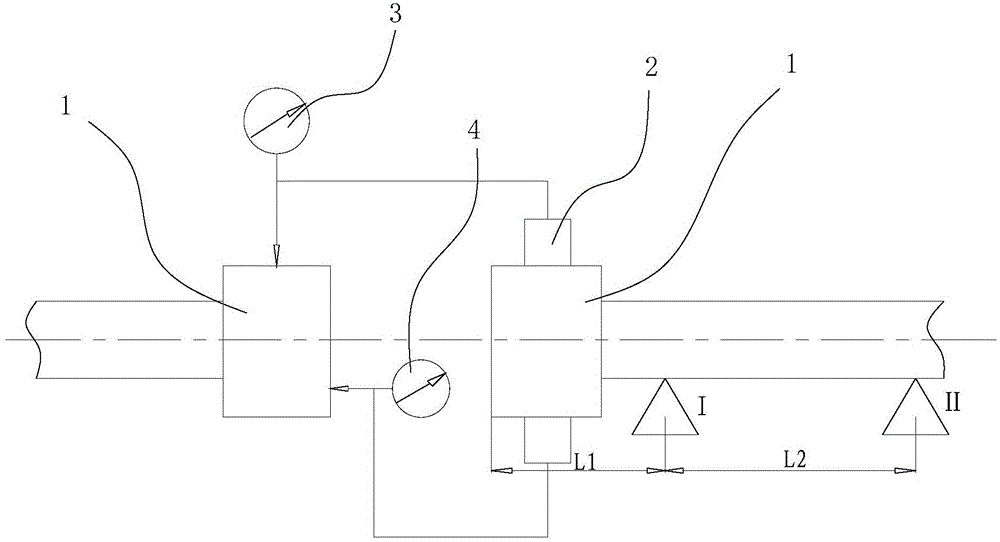
[0092] like figure 2 As shown, it is a schematic diagram of the alignment of the motor shaft and the transmission shaft. The shaft installation and alignment method of the present invention is used to align the rotating shaft of the motor and the transmission shaft.

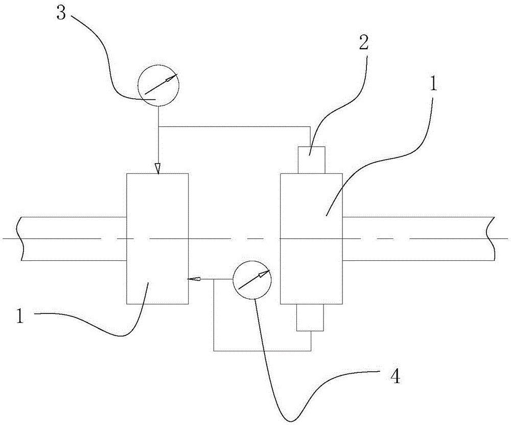
[0093] like figure 2 As shown, first install the coupling 1 on the two connecting shafts that need to be connected; then realize the installation alignment through the following steps.

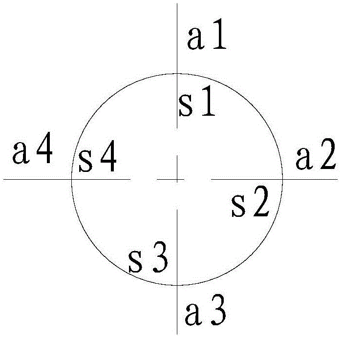
[0094] 1) Determine the transmission shaft as the reference shaft and the motor shaft as the adjustment shaft, and measure the radial deviation a in the vertical direction of the coupling 1 on the adjustment shaft relative to the coupling 1 on the reference shaft through the measuring device 竖 , the radial deviation a in the horizontal direction 水 , the end face deviation S in the vertical direction 竖 , the end face deviation S in the horizontal direction 水 ; the end face deviation S in the vertical direction 竖 Refers to ...


PUM


Abstract

The invention discloses an installation aligning method for a shafting. Adjustment is easy and convenient, and meanwhile adjusting accuracy is high. The aligning method includes the steps that couplings are installed on two connecting shafts, and the relative radial deviation and end face deviation between the couplings on the two connecting shafts are measured in the vertical direction and the horizontal direction; the positions of the two connecting shafts are adjusted according to the radial deviation and end face deviation in the horizontal direction, and the axes of the connecting shafts are located in the same vertical plane; then the adjusting quantities of adjusting gaskets of supports at the positions from the first fulcrum to the nth fulcrum of the adjusting shaft are calculated according to the detected end face deviation and radial deviation in the vertical direction; and it is guaranteed that the position of the reference shaft is unchanged, the thicknesses of the adjusting gaskets of the corresponding supports at the positions from the first fulcrum to the nth fulcrum of the adjusting shaft are adjusted according to the acquired adjusting quantities of the adjusting gaskets, and then the two connecting shafts are coaxial. By the adoption of the aligning method, the steps are simple, operation is easy and convenient, aligning time is shortened, and adjusting accuracy is guaranteed.

Description

technical field [0001] The invention relates to an installation and adjustment method, in particular to a shaft installation and alignment method. Background technique [0002] It is well known that primary fans in thermal power plants are generally divided into two types: axial flow and centrifugal fans. Centrifugal fans are characterized by simple structure, high efficiency and low energy consumption, so they are widely used. However, in practical use, centrifugal fans are reliable in operation. There are many reasons for poor performance, such as design structure, manufacturing quality, etc. From the perspective of installation reasons, the shaft alignment quality directly affects the key factors in the later operation of the centrifugal fan, so improving the shaft alignment quality and speed will not affect the later stage. The operation quality has a good guarantee effect. SUMMARY OF THE INVENTION [0003] The technical problem to be solved by the present invention i...

Claims


Application Information

Patent Timeline
IPC IPC(8): B23P19/10G01B5/00
CPCB23P19/10G01B5/00
Inventor 穆遵明王成福方健
Owner SEPCO ELECTRIC POWER CONSTR CORP
Learn More